


OL-30824-01 17
Front Panel Description
Front Panel Description
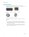
The front panel of your residential gateway provides LED status indicators that
indicate how well and at what state your residential gateway is operating. See Front
Panel LED Status Indicator Functions (on page 102), for more information on front
panel LED status indicator functions.
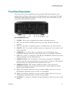
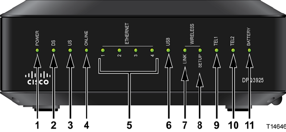
Model DPQ3925 shown here
1 POWER—ON, power is applied to the wireless residential gateway
2 DS—ON, the wireless residential gateway is receiving data from the cable
network
3 US—On, the wireless residential gateway is sending data to the cable network
4 ONLINE—ON, the wireless residential gateway is registered on the network and
fully operational
5 ETHERNET 1 - 4—ON, a device is connected to one of the Ethernet ports.
BLINKING indicates that data is being transferred over the Ethernet connection
6 USB—ON, a device is connected to the USB port. BLINKING indicates that data is
being transferred over the USB connection
7 WIRELESS LINK—ON, the Wireless Access Point is operational. BLINKING
indicates that data is being transferred over the wireless connection. OFF indicates
that the wireless access point has been disabled by the user
8 WIRELESS SETUP—OFF (normal condition) wireless setup is not active.
BLINKING indicates the user has activated wireless setup to add new wireless
clients on the wireless network
9 TEL1—ON indicates telephony service is enabled. Blinks when line 1 is in use.
OFF indicates that phone service for TEL 1 is not enabled
10 TEL2—ON indicates telephony service is enabled. Blinks when line 2 is in use.
OFF indicates that phone service for TEL 2 is not enabled
11 BATTERY—If a battery is included, this light illuminates when the battery is fully
charged