


18 OL-30824-01
Back Panel Description
Back Panel Description
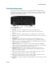
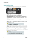
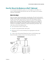
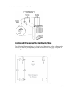
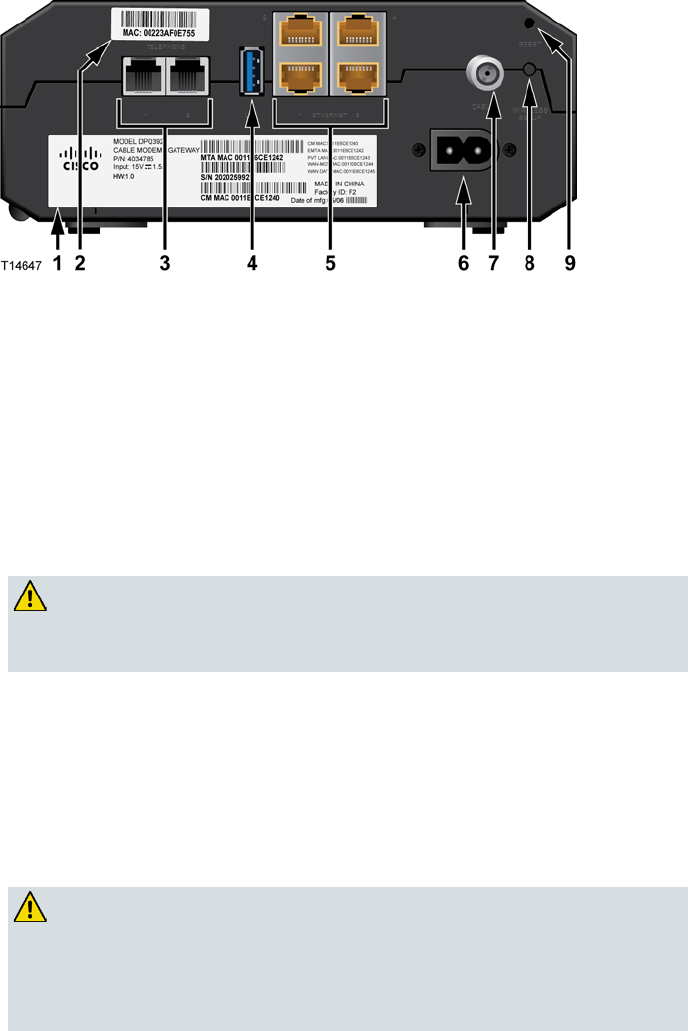
The following illustrations show the description and function of the back panel
components on the Cisco DPQ3925 residential gateway.
1 LABEL—Displays technical information regarding the gateway
2 MAC ADDRESS LABEL—Displays the MAC address of the residential gateway
3 TELEPHONE 1 and 2—RJ-11 telephone ports connect to home telephone wiring to
conventional telephones or fax machines
4 USB—Connects to selected client devices
5 ETHERNET—Four RJ-4
5 Ethernet ports connect to the Ethernet port on your PC or
your home network
6 POWER—Connects the residential gateway to the AC power cord that is provided
with your residential gateway
CAUTION:
Avoid damage to your equipment. Only use the power cord that
is provided with your residential gateway.
7 CABLE—F-connector connects to an active cable signal from your service provider
8 WIRELESS SETUP—Pressing this switch initiates wireless setup, this feature allows
the user to add new Wi-Fi Protected Setup (WPS™) compliant wireless clients to the
home network
9 RESET—A momentary pressing (1-2 seconds) of this switch reboots the EMTA.
Pressing the switch for more than ten seconds first causes a reset-to-factory-
default of
all settings and then reboots the gateway
CAUTION:
The Reset button is for maintenance purposes only. Do not use
unless instructed to do so by your cable or telephone service
provider. Doing so may cause you to lose any cable modem
settings you have selected.