


13
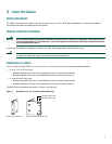
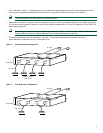
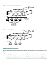
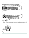
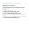
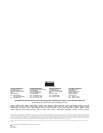
Step 3 Connect the DC-input end of the cable to a Cisco RPS rear-panel connector as shown in Figure 14 or Figure 15.
Figure 14 Connecting a One-to-One Cable to a Cisco RPS for Quasi-Redundant Power
Figure 15 Connecting a Two-to-One Y-Cable to a Cisco RPS for Fully Redundant Power
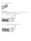
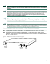
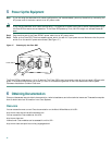
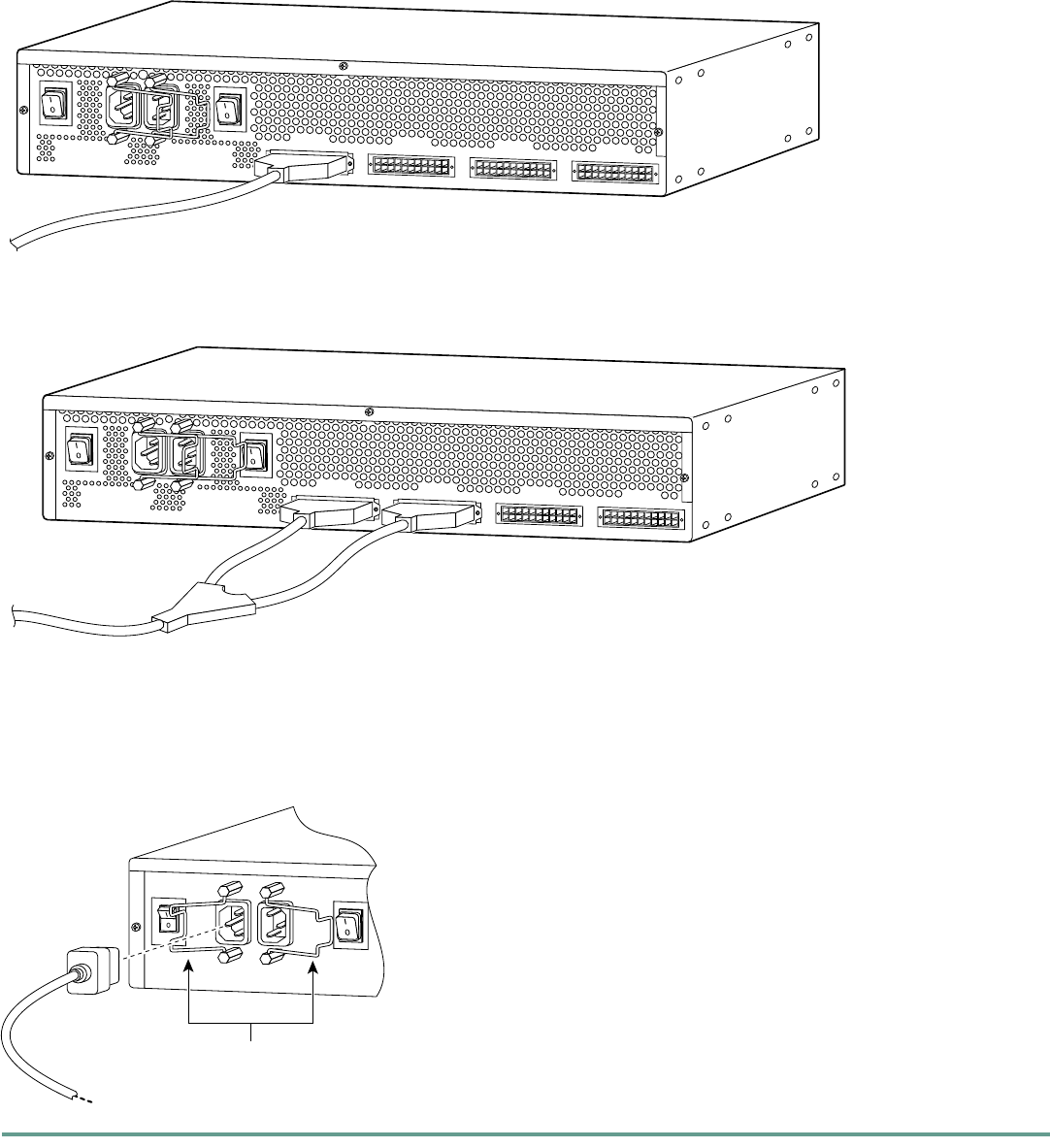
Step 4 On the Cisco RPS rear panel, connect one or two AC power cables. A single AC power cable can go into either AC
connector. Two AC power cables provide parallel AC power sources. Use the cable locks on the Cisco RPS to lock the
cables in place. (See Figure 16.)
Figure 16 Connecting AC Power Cables to the Cisco RPS
88108
AC INPUT 1
100-200 V~ 50/60 Hz
10-5 A 1000 W
AC INPUT 2
100-200 V~ 50/60 Hz
10-5 A 1000 W
DC OUTPUT 1
DC OUTPUT 2
DC OUTPUT 3
DC OUTPUT 4
88107
AC INPUT 1
100-200 V~ 50/60 Hz
10-5 A 1000 W
AC INPUT 2
100-200 V~ 50/60 Hz
10-5 A 1000 W
DC OUTPUT 1
DC OUTPUT 2
DC OUTPUT 3
DC OUTPUT 4
29092
Cable locks