


2-52
Cisco ASR 9000 Series Aggregation Services Router Overview and Reference Guide
OL-17501-09
Chapter 2 Functional Description
Power System Functional Description
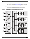
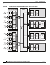
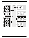
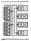
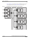
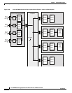
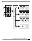
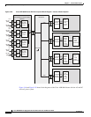
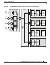
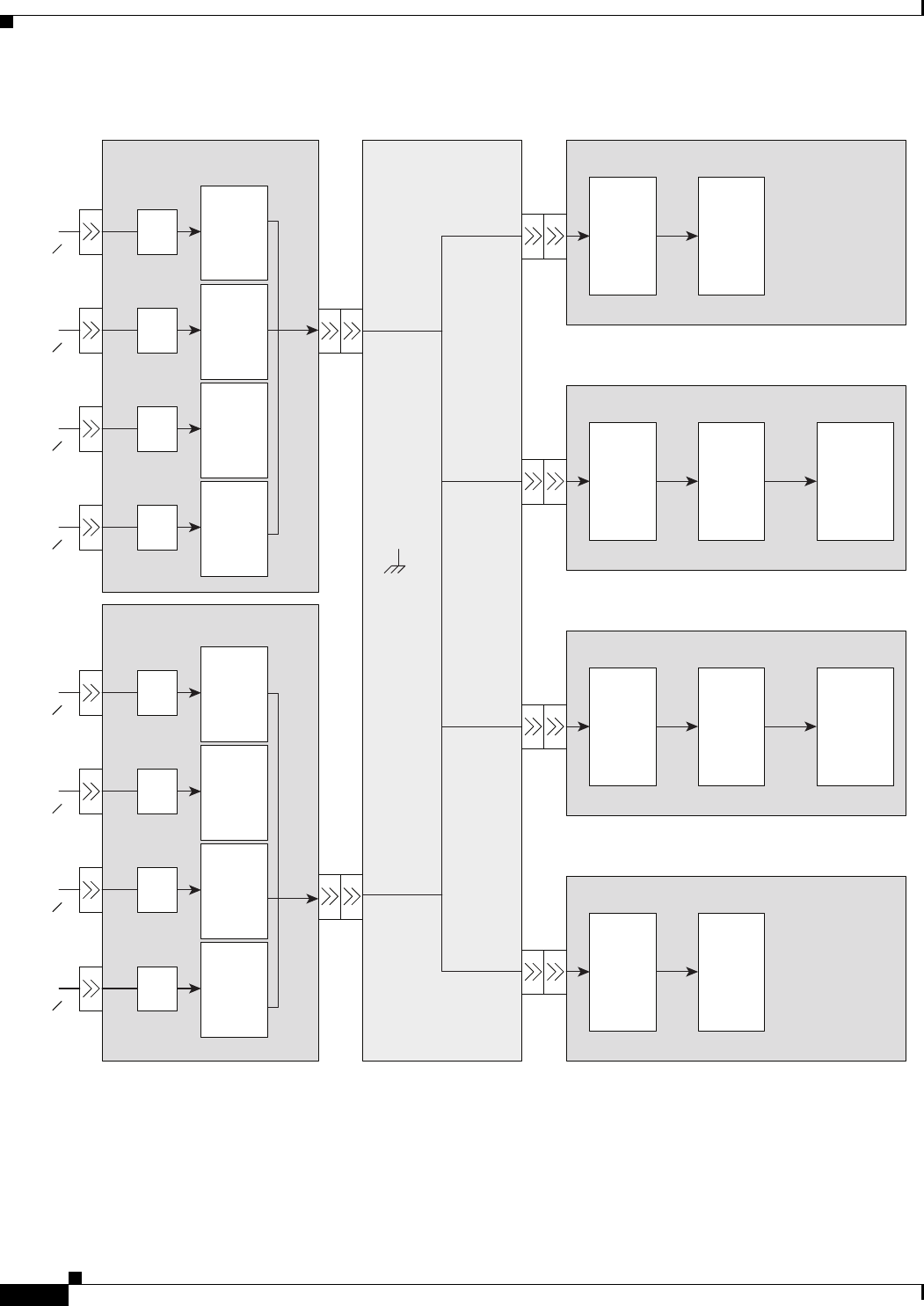
Figure 2-42 Cisco ASR 9010 Router AC Power System Block Diagram—Version 2 Power System
AC Power Shelf-0
w/AC/DC Power Supply Modules
Power Distribution
Backplane
–54V
–54V
–54V
–54V RTN
–54V
–54V
24402
AC Power Shelf-1
w/AC/DC Power Supply Modules
–54V
AC/DC
Pwr Sply
Module-
PM0
3 KW
EMI
Filter
AC1-1
220V
20A 1O
AC/DC
Pwr Sply
Module-
PM1
3 KW
EMI
Filter
AC1-2
220V
20A 1O
AC/DC
Pwr Sply
Module-
PM2
3 KW
EMI
Filter
AC1-3
220V
20A 1O
AC/DC
Pwr Sply
Module-
PM3
3 KW
EMI
Filter
AC1-4
220V
20A 1O
AC/DC
Pwr Sply
Module-
PM4
3 KW
EMI
Filter
AC2-1
220V
20A 1O
AC/DC
Pwr Sply
Module-
PM5
3 KW
EMI
Filter
AC2-2
220V
20A 1O
AC/DC
Pwr Sply
Module-
PM6
3 KW
EMI
Filter
AC2-3
220V
20A 1O
AC/DC
Pwr Sply
Module-
PM7
3 KW
EMI
Filter
AC2-4
220V
20A 1O
Fan Tray 0
–54V
Soft-Start
Circuit,
EMI Filter
Fan
Controller
and
Cooling
Fans
Fan Tray 1
Soft-Start
Circuit,
EMI Filter
Fan
Controller
and
Cooling
Fans
–54V
Line Card (x8)
Soft-Start
Circuit,
EMI Filter
Narrow
Range,
Fixed
Ratio
(5:1)
10.8V
Converter
Point of
Load
(POL)
Converters
–54V –10.8V
RSP Card (x2)
Soft-Start
Circuit,
EMI Filter
Narrow
Range,
Fixed
Ratio
(5:1)
10.8V
Converter
Point of
Load
(POL)
Converters
–54V –10.8V