


2-79
Cisco ASR 9000 Series Aggregation Services Router Overview and Reference Guide
OL-17501-09
Chapter 2 Functional Description
Cooling System Functional Description
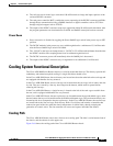
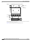
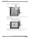
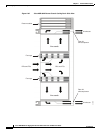
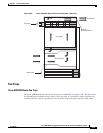
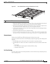
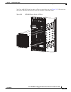
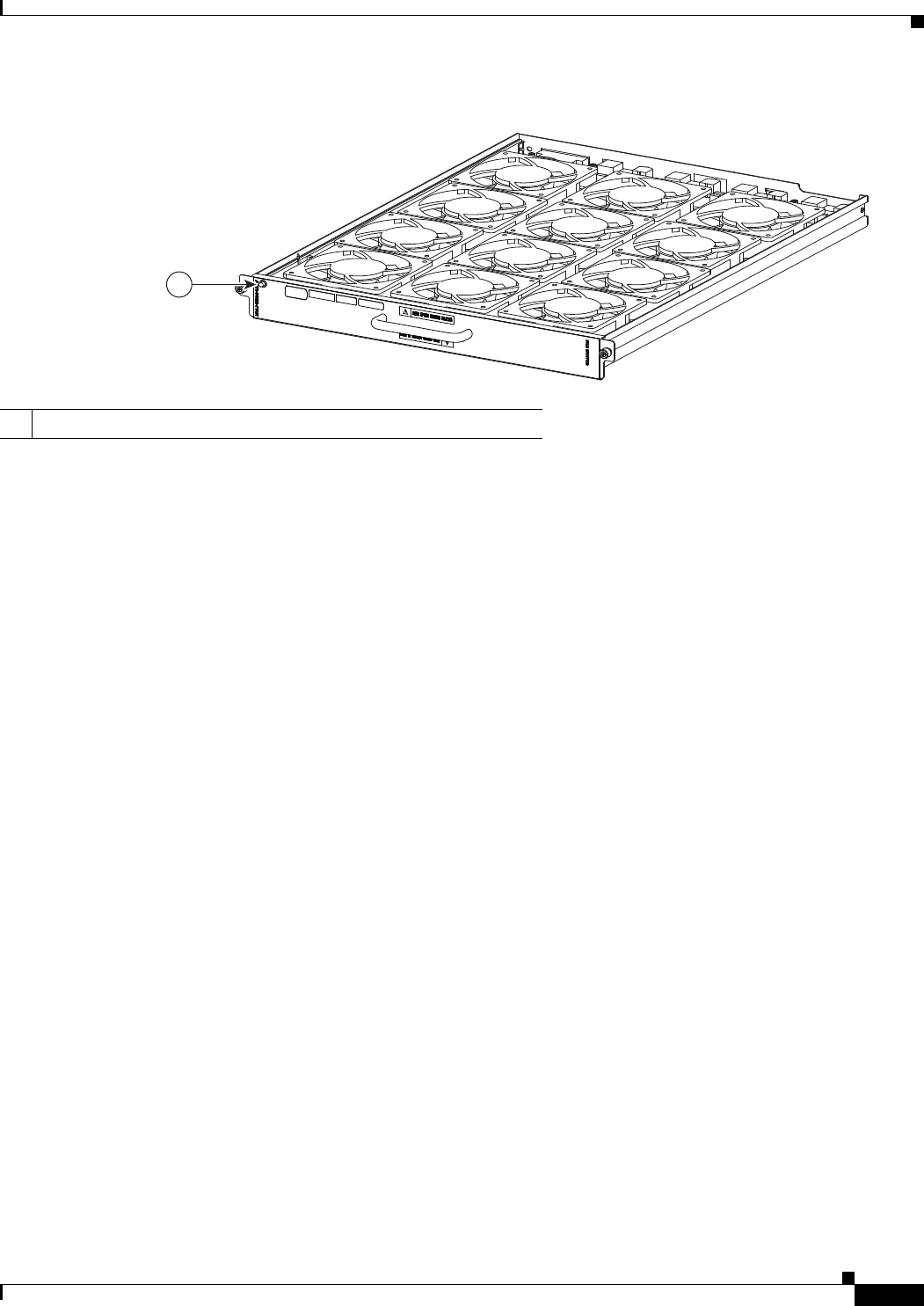
Figure 2-72 Cisco ASR 9922 Router and Cisco ASR 9912 Router Fan Tray
• The fan tray contains 12 axial 120-mm (4.72-in) fans. There is a fan control board at the back end
of each tray with a single power/data connector that connects with the backplane.
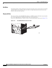
• The fan tray aligns through two guide pins inside the chassis, and it is secured by two captive screws.
The controller board floats within the fan tray to allow for alignment tolerances.
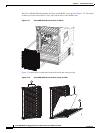
• A finger guard is adjacent to the front of most fans to keep fingers away from spinning fan blades
during removal of the fan tray.
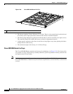
• The maximum weight of the fan tray is 18.00 lb (8.16 kg).
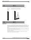
• The fan tray width is increased from 16.3 inches to 17.3 inches. The overall fan tray depth remains
the same at 23 inches. The individual fan current rating is increased to 2 A to support higher speeds.
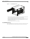
Status Indicators
The fan tray has a Run/Fail status LED on the front panel to indicate fan tray status.
After fan tray insertion into the chassis, the LED lights up temporarily appearing yellow. During normal
operation:
• The LED lights green to indicate that all fans in the module are operating normally.
• The LED lights red to indicate a fan failure or another fault in the fan tray module. Possible faults
are:
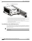
–
Fan stopped.
–
Fans running below required speed to maintain sufficient cooling.
–
Controller card has a fault.
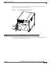
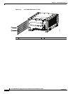
Fan Tray Servicing
No cables or fibers must be moved during installation or removal of the fan tray(s). Replacing fan trays
does not interrupt service.
1 Fan tray status LED
302356
1