


2-14
Cisco ASR 9000 Series Aggregation Services Router Overview and Reference Guide
OL-17501-09
Chapter 2 Functional Description
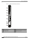
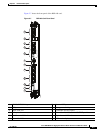
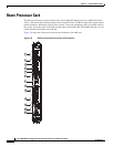
Route Processor Card
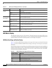
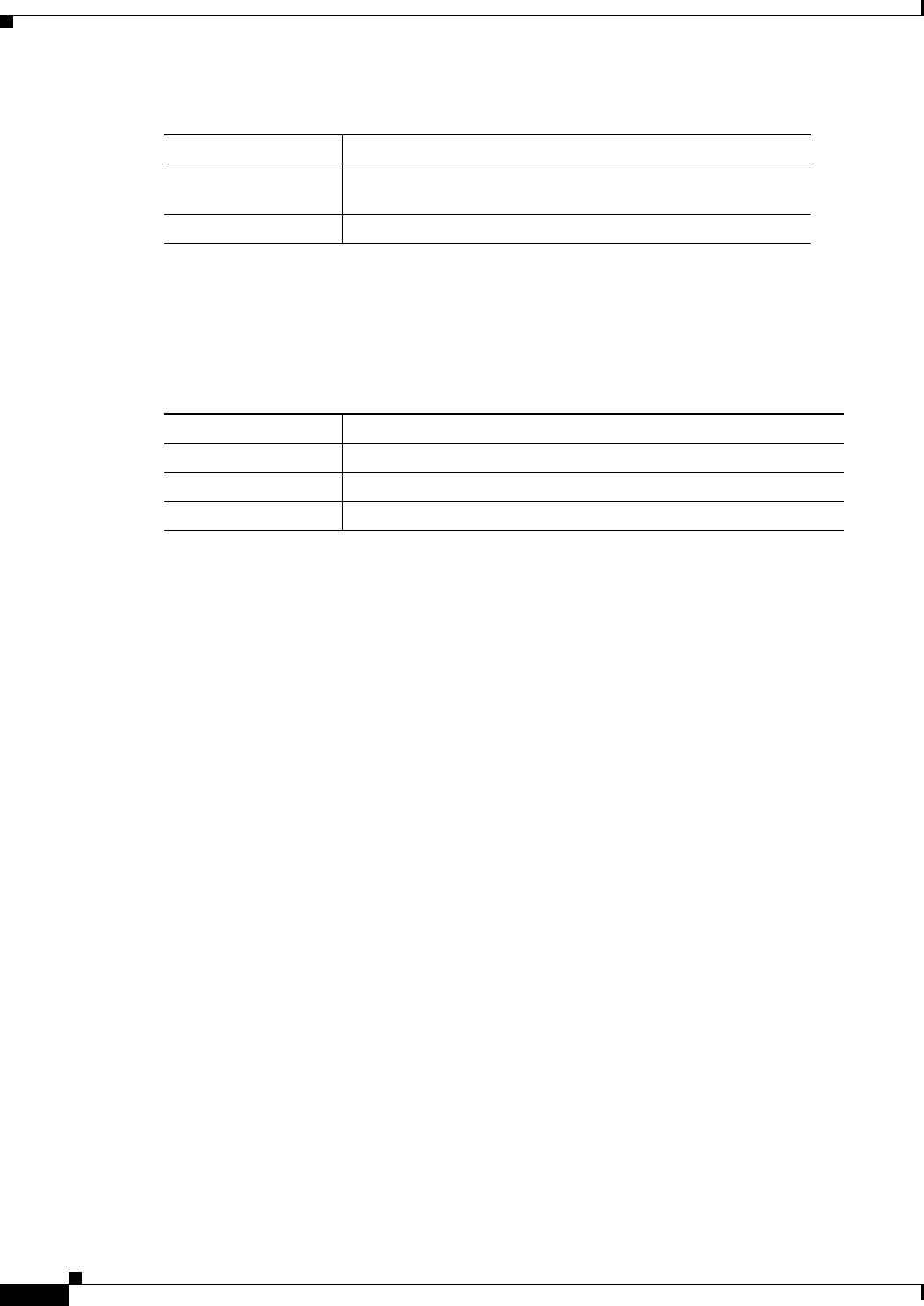
LED Matrix CAN Bus Controller Error Display
Table 2-5 shows the error messages the LED matrix displays if the RSP card fails one of the power on self
tests.
Push Buttons
Two push buttons are provided on the RSP/RP card front panel.
• Alarm Cutoff (ACO)—ACO activation suppresses alarm outputs. When the ACO button is pushed
while critical alarms are active, the ACO LED turns on and the corresponding alarm output contacts
revert to the normally open (non-alarm) state, thus suppressing the alarm. If subsequent critical
alarms are detected and activated after the ACO activation, the ACO function is deactivated to notify
the user of the arrival of the new alarm(s). In this case, the ACO LED will turn off and any active
alarms are again indicated by driving their alarm output contacts to the alarm state.
• Lamp Test—When the Lamp Test button is pushed, the RSP/RP status LED, line card status and port
LEDs, and Fan Tray LEDs light until the button is released. The LED matrix display is not affected.
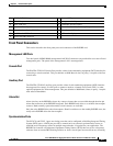
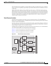
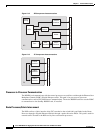
Functional Description
The switch fabric and route processor functions are combined on a single RSP card in the
Cisco ASR 9010 Router, Cisco ASR 9006 Router, and Cisco ASR 9904 Router. In the
Cisco ASR 9922 Router and Cisco ASR 9912 Router, the route processor functions are on the RP card.
whereas the switch fabric is on the FC card. The RSP/RP card also provides shared resources for
backplane Ethernet, timing, and chassis control. Redundant RSP/RP cards provide the central point of
control for chassis provisioning, management, and data-plane switching.
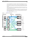
Switch Fabric
The switch fabric portion of the RSP card links the line cards together. The switch fabric is configured
as a single stage of switching with multiple parallel planes. The fabric is responsible for getting packets
from one line card to another, but has no packet processing capabilities. Each fabric plane is a
single-stage, non-blocking, packet-based, store-and-forward switch. To manage fabric congestion, the
RSP card also provides centralized Virtual Output Queue (VOQ) arbitration.
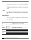
ACT The RSP/RP is active (IOS-XR completely up and ready for
traffic)
STBY The RSP/RP is standby (IOS-XR completely up and ready)
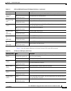
Table 2-4 RSP-440 and RP LED Matrix Boot Stage and Runtime Display (continued)
LED Matrix Display Description
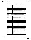
Table 2-5 RSP LED Matrix CAN Bus Controller Status Display
LED Matrix Display Description
PST1 Failed DDR RAM memory test
PST2 Failed FPGA image cyclic redundancy checking (CRC) check
PST3 Failed card type and slot ID verification