


1-17
Cisco ASR 9000 Series Aggregation Services Router Getting Started Guide
OL-17502-02
Chapter 1 Introducing the Cisco ASR 9000 Series Aggregation Services Router
System Configurations
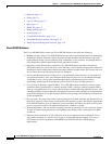
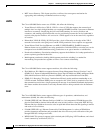
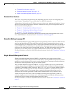
Figure 1-1 6-Slot Chassis
243377
Line card 3
FT0
M0 M1 M2
FT1
Line card 2
Line card 1
Line card 0
RSP1
RSP0
Slot 5
Slot 4
Slot 3
Slot 2
Slot 1
Slot 0
Power shelf
Power modules
Fan trays
RSP cards
Line cards
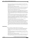
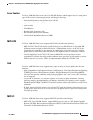
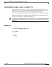
Figure 1-2 10-Slot Chassis
242689
Line card
Line card
Line card
Line card
RSP0
RSP1
FT0
FT1
Front air intake
Line card
Line card
Line card
Line card
Slot 0
Slot 1
Slot 2
Slot 3
Slot 4
Slot 5
Slot 6
Slot 7
Slot 8
Slot 9
Power shelves
PS0
PS1
Power modules
M0 M1 M2
M0 M1 M2
Line cards 0-3
Fan trays
Line cards 4-7
RSP cards
0123 4567
Each chassis type supports 40G per slot, and can share route-switch processors (RSPs) and line cards
(LCs), which are interchangeable. In each chassis, two slots are designated for RSPs, while the
remaining slots accommodate line cards that carry the traffic. The RSPs interconnect the line cards and
provide chassis management and control. Any line card can be used as a network-facing trunk card, a
subscriber-facing card, or it can provide any other form on connectivity.