


B-7
Catalyst 3850 Switch Hardware Installation Guide
OL-26779-02
Appendix B Connector and Cable Specifications
Cable and Adapter Specifications
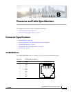
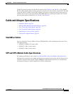
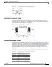
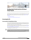
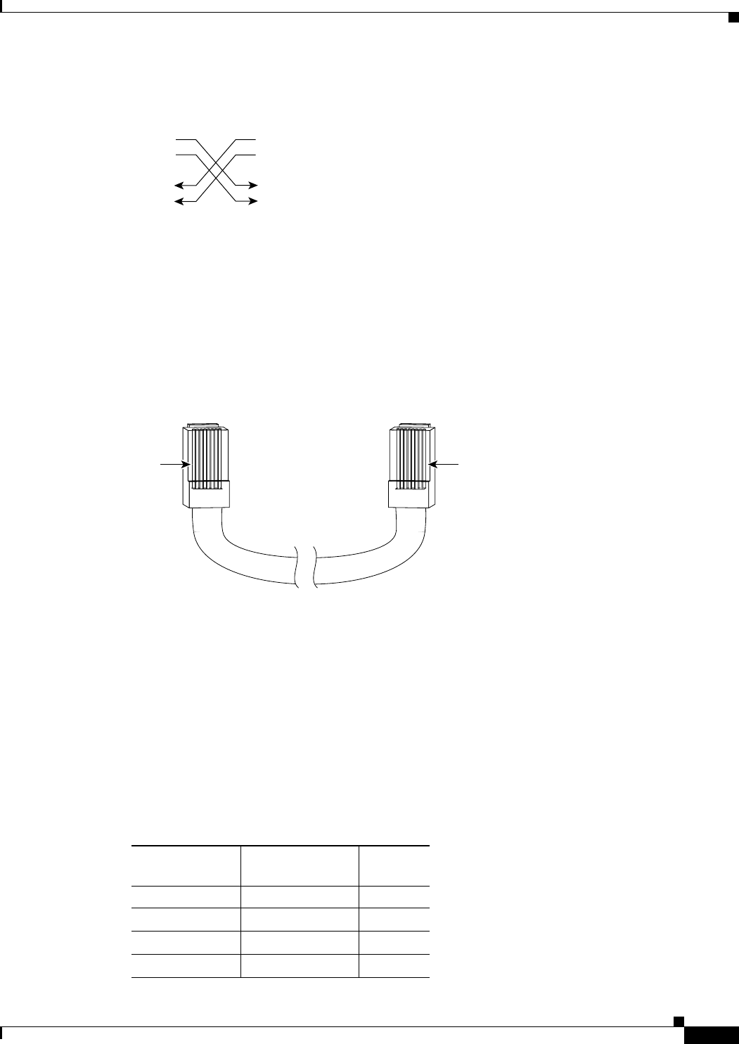
Figure B-13 Two Twisted-Pair Crossover Cable Schematic
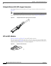
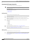
Identifying a Crossover Cable
To identify a crossover cable, hold the cable ends side-by-side, with the tab at the back. The wire
connected to the pin on the outside of the left plug should be the same color as the wire connected to the
pin on the outside of the right plug. (See Figure B-14.)
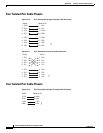
Figure B-14 Identifying a Crossover Cable
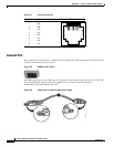
Console Port Adapter Pinouts
The console port uses an 8-pin RJ-45 connector, which is described in Table B-1 and Table B-2. If you
did not order a console cable, you need to provide an RJ-45-to-DB-9 adapter cable to connect the switch
console port to a PC console port. You need to provide an RF-45-to-DB-25 female DTE adapter if you
want to connect the switch console port to a terminal. You can order a kit with an adapter (part
number ACS-DSBUASYN=). For console port and adapter pinout information, see Table B-1 and
Table B-2.
Table B-1 lists the pinouts for the console port, the RF-45-to-DB-9 adapter cable, and the console device.
Switch
3 TD+
6 TD–
1 RD+
2 RD–
Switch
3 TD+
6 TD–
1 RD+
2 RD–
H5579
Pin 1
H10632
Pin 8
Pin 1 on one connector and
pin 8 on the other connector
should be the same color.
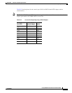
Table B-1 Console Port Signaling Using a DB-9 Adapter
Switch Console
Port (DTE)
RJ-45-to-DB-9
Terminal Adapter
Console
Device
Signal DB-9 Pin Signal
RTS 8 CTS
DTR 6 DSR
TxD 2 RxD