


12
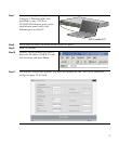
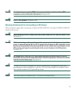
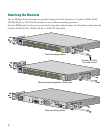
Attaching the Brackets
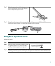
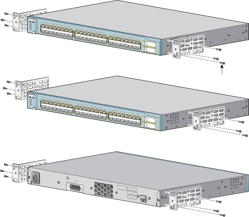
Use six Phillips flat-head screws to attach the long side of the brackets to Catalyst 2950G-48-EI,
2950SX-48-SI, or 2950T-48-SI switches in one of three mounting positions.
Use four Phillips flat-head screws to attach the long side of the brackets for all switches other than the
Catalyst 2950G-48-EI, 2950SX-48-SI, or 2950T-48-SI models.
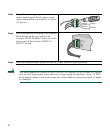
RATING
100-127V~
@
1A
200-240V~
@
0.5A
50-60Hz
DC INPUT FOR REMOTE
POW
ER SUPPLY
SPECIFIED IN MANUAL.
+12V @
4.5A
CONSOLE
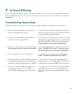
Catalyst 2950
SERIES
1
X
2
X
1
7
X
1
8
X
3
3
X
3
4
X
1
5
X
1
6
X
3
1
X
3
2
X
4
7
X
4
8
X
1
2
3
4
5
6
7
8
9
10
11
12
13
14
15
16
17
18
19
20
21
22
23
24
25
26
27
28
29
30
31
32
33
34
35
36
37
38
39
40
41
42
43
44
45
46
47
1
48
2
SYST
RPS
STAT
UTIL
DUPLX
SPEED
MODE
Catalyst 2950
SERIES
1
X
2
X
1
7
X
1
8
X
3
3
X
3
4
X
1
5
X
1
6
X
3
1
X
3
2
X
4
7
X
4
8
X
1
2
3
4
5
6
7
8
9
10
11
12
13
14
15
16
17
18
19
20
21
22
23
24
25
26
27
28
29
30
31
32
33
34
35
36
37
38
39
40
41
42
43
44
45
46
47
1
48
2
SYST
RPS
STAT
UTIL
DUPLX
SPEED
MO
DE
Front-mounting position
Mid-rack-mounting position (telco rack)
Rear-mounting position
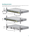
Number-8 Phillips
flat-head screws