


16-8
Cisco ONS 15310-CL Ethernet Card Software Feature and Configuration Guide, R5.0
June 2005
Chapter 16 CE-100T-8 Ethernet Operation
CE-100T-8 SONET Circuits and Features
CE-100T-8 STS/VT Allocation Tab
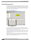
The CE-100T-8 has two pools, each with a maximum capacity of three STSs. At the CTC card-level view
under the Maintenance tab, the STS/VT Allocation tab displays how the provisioned circuits populate
the two pools. This information can be useful in freeing up the bandwidth required for provisioning a
circuit, if there is not enough existing capacity on any one pool for provisioning the desired circuit. The
user can look at the distribution of the existing circuits among the two pools and decide which circuits
to delete in order to free up space for the desired circuit.
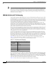
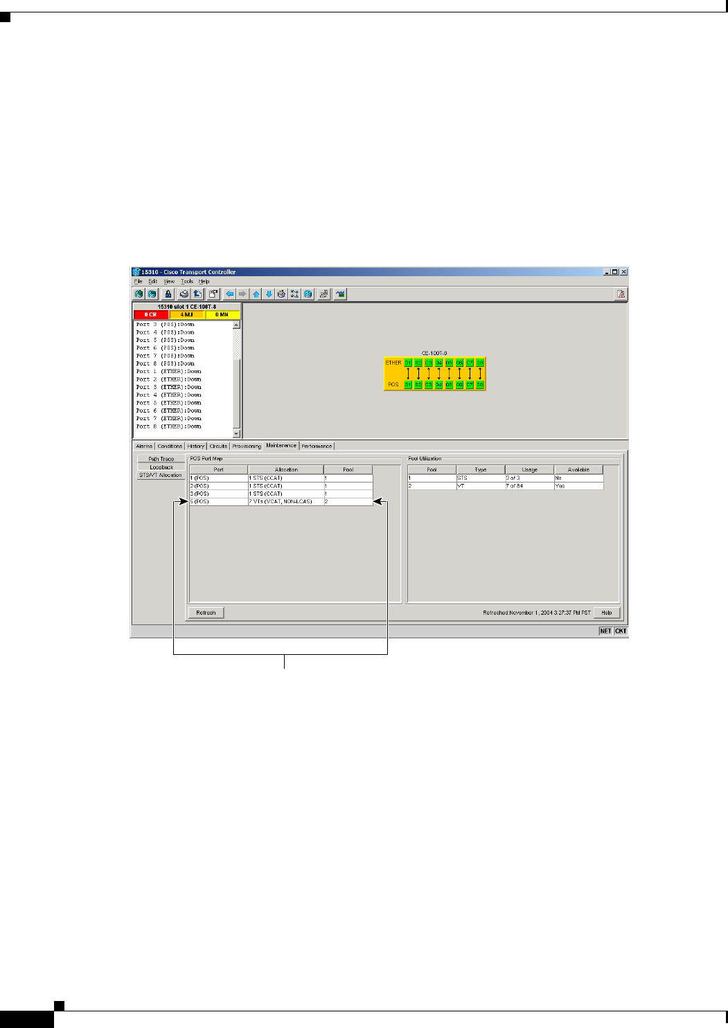
Figure 16-4 CE-100T-8 STS/VT Allocation Tab
For example if a user needs to provision an STS-3c or STS-1-3v on the CE-100T-8 card shown in
Figure 16-4, an STS-3c or STS-1-3v worth of bandwidth is not available from either of the two pools.
The user needs to delete circuits from the same pool to free up bandwidth. If the bandwidth is available
but scattered among the pools, the circuit cannot be provisioned.
Looking at the POS Port Map table, the user can determine which circuits belong to which pools. The
Pool and Port columns in Figure 16-4 show that the circuit on port 5 is drawn from Pool 2, and no other
circuits are drawn from Pool 2. Deleting this one circuit will free up an STS-3c or STS-1-3v worth of
bandwidth from a single pool.
The POS Port table has a row for each port with three columns (Figure 16-4). They show the port
number, the circuit size and type, and the pool it is drawn from. The Pool Utilization table has two
columns and shows the pool number, the type of circuits on that pool, how much of the pool’s capacity
is being used, and whether additional capacity is available.
124894
Port 5 belongs to Pool 2