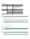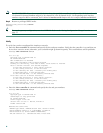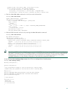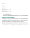
41
Configuring a Channelized T1 or E1 DFC
This section shows how to configure channelized T1 or E1. On a Cisco AS5350 or Cisco AS5400, you can allocate the available
channels for channelized E1 and T1 in the following ways:
• All channels can be configured to support ISDN PRI.
• If you are not running ISDN PRI, all channels can be configured to support robbed-bit signaling (also known as
channel-associated signaling).
• All channels can be configured in a single channel group.
• Mix and match channels supporting ISDN PRI, channel grouping, and channel-associated signaling (CAS).
• Mix and match channels supporting ISDN PRI, channel grouping, and robbed-bit signaling across the same T1 line. For
example, on the same channelized T1 you can configure the pri-group timeslots 1-10,24 command, channel-group 11
timeslots 11-16 command, and ds0-group 17 timeslots 17-23 type e&m-fgb command. This is an unusual configuration
because it requires you to align the correct range of time slots on both ends of the connection.
Note For configuration information about leased-line or nondial use, see the Configuration Fundamentals Configuration
Guide, available online. You can access this document at Cisco Product Documentation > Cisco IOS Software >
Cisco IOS Software Release you are using > Configuration Guides and Command References > Configuration guide for
your application.
Note The CT1/E1 controller numbering convention is dfc-slot/port in CLI commands. DFC slot numbering starts from the
motherboard and works up from left to right. Slot 0 is reserved for the motherboard. The CT1/E1 DFC slots are
numbered sequentially from 1 to 7. Port numbering is from 0 to 7.
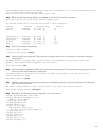
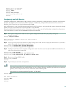
Step 1 Use the enable command and password to enter privileged EXEC mode. You are in privileged EXEC mode when the
prompt changes to Gateway#.
Gateway> enable
Password: password
Gateway#
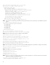
Step 2 Enter global configuration mode. You are in global configuration mode when the prompt changes to Gateway(config)#.
Gateway# configure terminal
Enter configuration commands, one per line. End with CNTL/Z.
Gateway(config)#
Step 3 Enter controller configuration mode to configure your controller slot and port. Slot values range from 1 to 7. Port
values range from 0 to 7 for T1 and E1.
Gateway(config)# controller [t1 | e1] slot/port
Gateway(config-controller)#
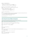
Step 4 Enter your telco’s framing type for the CT1 controller, either esf or sf:
Gateway(config-controller)# framing esf
or
Enter the framing type for the CE1 controller:
Gateway(config-controller)# framing crc4
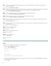
Step 5 Define the line code as binary 8 zero substitution (B8ZS) for the CT1 controller:
Gateway(config-controller)# linecode b8zs
or
Define the line code as high-density bipolar 3 (HDB3) for the CE1 controller:
Gateway(config-controller)# linecode hdb3


