


16 Token Ring Interface Processor (TRIP) Installation and Configuration
Installation
List of Parts and Tools
Verify that you have all of the parts and optional equipment you will need to install the TRIP. If you
need additional equipment, contact a service representative for ordering information.
• One TRIP
• One Token Ring 802.5 media attachment unit (MAU) and Token Ring adapter cable for each port
on TRIP
• 9-pin male connector for each Token Ring connector on TRIP
• Grounding wrist strap
A disposable ESD-prevention wrist strap is included with all new components and upgrade kits; use
it to prevent damage to equipment from electrostatic discharge.
• If you are replacing the existing TRIP in your system, you also need a replacement TRIP.
• A large Phillips or flat-blade screwdriver for the captive installation screws that secure the TRIP
in its slot.
• Antistatic mat or antistatic foam (only if you are replacing components such as the ROM)
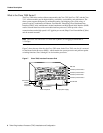
Installation
The following sections describe the procedures for removing or installing a TRIP in a Cisco 7000
and Cisco 7500 series router. The OIR function allows you to install and remove a TRIP without first
shutting down the system; however, you must follow the instructions carefully. Failure to insert the
TRIP properly can cause system error messages indicating a board failure. For a complete
description of OIR, refer to the section “Online Insertion and Removal—An Overview” on page 13.
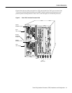
Each unused interface processor slot contains an interface processor filler (which is an interface
processor carrier without an interface board) to keep dust out of the chassis and to maintain proper
air flow through the interface processor compartment. If you are installing a new TRIP that is not a
replacement, you must first remove the interface processor filler from an unused slot, proceed to the
section “Removing an Interface Processor Filler.” If you are replacing a TRIP, proceed to the section
“Removing a TRIP.”
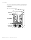
Removing an Interface Processor Filler
Select an unused interface processor slot for the new TRIP and remove the interface processor filler
as follows:
Step 1 Choose an available slot for the TRIP and ensure that there is enough clearance to
accommodate any interface equipment that you will connect directly to the ports (for
example, transceivers that connect directly to the ports overlap equipment on adjacent
interface processors).
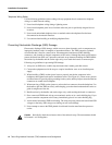
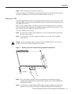
Step 1 Use a screwdriver to loosen the captive installation screws on the interface processor filler.
(See Figure 10.)
Step 2 Place your thumbs on both ejectors and simultaneously pull them both outward to release
the TRIP from the backplane connector (in the opposite direction from that shown in
Figure 10c).
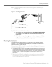
Step 3 Grasp the handle with one hand and pull the fillerstraight out of the slot, keeping your other
hand under the carrier to guide it. (See Figure 11.) Keep the carrier parallel to the
backplane.