


Token Ring Interface Processor (TRIP) Installation and Configuration 9
Product Description
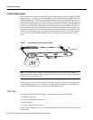
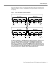
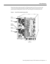
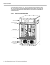
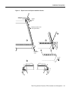
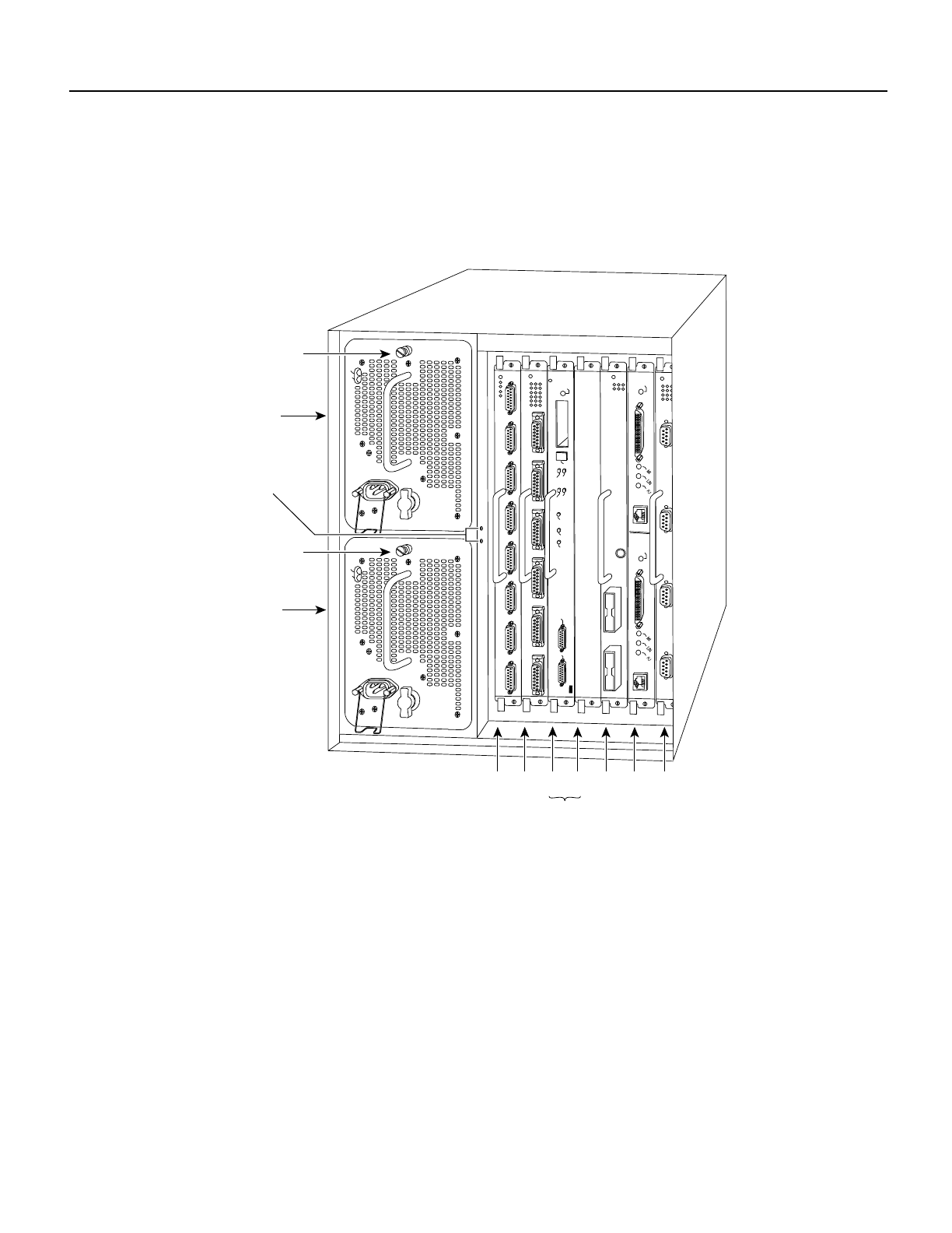
Figure 8 shows the rear of the seven-slot Cisco 7507 router. In the Cisco 7507, up to two slots (2 and
3) are reserved for the Route Switch Processor (RSP2), which contains the system processor and
performs packet switching functions. Slots 0 and 1, and 4 through 6 are for interface processors.
Figure 8 Cisco 7507, Interface Processor End
ENABLE
ENABLE
EJECT
SLOT 0
SLOT 1
NORMAL
CPU HALT
RESET
AUX.
CONSOLE
ROUTE SWITCH PROCESSOR 2
SLAVE
MASTER
SLAVE/MASTER
H3888
Slot 0
1
2
34 5 6
U
pper
ower supply
C
hassis
g
rounding
e
ceptacles
L
ower
ower supply
I
O
DC FAIL
AC POWER
I
O
DC FAIL
AC POWER
RSP slots
C
aptive
n
stallation screw
C
aptive
n
stallation screw