


4028518 Rev B 33
Front Panel LED Status Indicator Functions
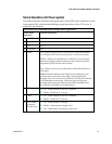
Normal Operations (AC Power applied)
The following chart illustrates the appearance of the LED status indicators on the
front panel of the cable modem during normal operations when AC power is
applied to the modem.
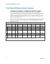
Front Panel LED Status Indicators During Normal Operations
Front Panel
Indicator
Normal Operations
1
POWER
On
2
DS
On
3
US
On
4
ONLINE
On
5
LINK
On – When a single device is connected to either the Ethernet
or USB port and no data is being sent to or from the modem
Blinks – When only one Ethernet or USB device is connected
and data is being transferred between the consumer premise
equipment (CPE) and the cable modem
Off – When no devices are connected to either the Ethernet or
USB ports
Note: With both Ethernet and USB devices connected to the
modem at the same time, when data is being transferred
through only one of the devices (Ethernet or USB), the indicator
will illuminate continuously. Whenever data is being sent
through both data ports (Ethernet and USB) simultaneously,
the indicator will blink as described above.
6
TEL1
On – When telephony service is enabled
Blinks – When line 1 is in use
7
TEL2
On – When telephony service is enabled
Blinks – When line 2 is in use
8
BATTERY
(optional
model only)
On – When battery is charged
Blinks – When battery charge is low
Off – When there is no battery in the unit