


19
4 Connecting Cables
This section describes how to do the cabling in the Cisco RFGW-10 UEQAM.
Power and Ground Connections
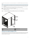
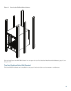
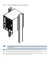
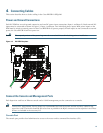
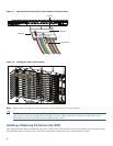
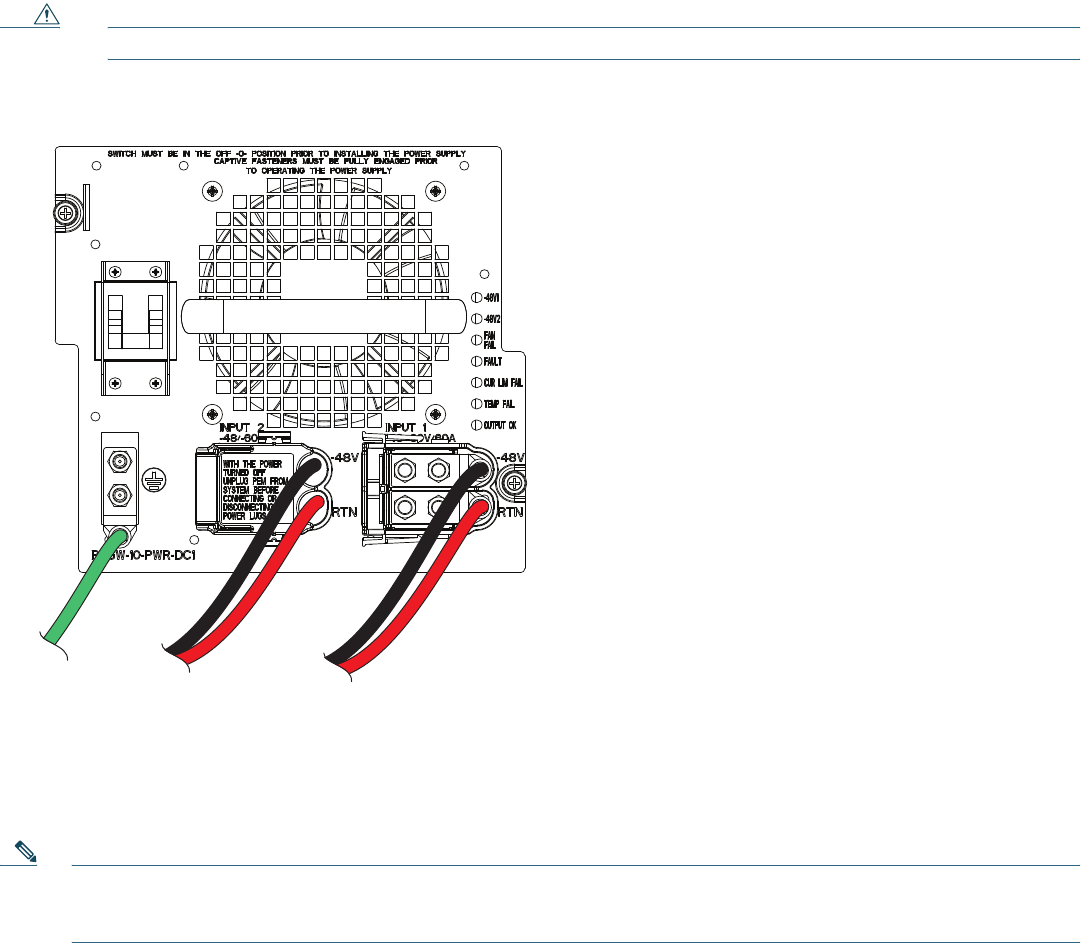
Each DC PEM has an earth ground connection and two DC power input connections (Input 1 and Input 2). Both external DC
inputs must be connected as shown in
Figure 13. Input 1 and Input 2 are individual power inputs. Both power inputs on the
PEM must be wired to external power for the Cisco RFGW-10 to operate properly. If both inputs are not connected to external
power, the Cisco RFGW-10 will not power on.
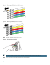
Caution The exposed portions of the power lugs must be covered with heat shrink tubing prior to installation.
Figure 13 DC PEM Faceplate
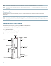
Connect the Console and Management Ports
Each Supervisor card has an Ethernet console and a 10/100 management port for connection to a console.
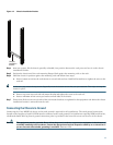
Note To meet FCC requirements, Ferrite clamps are recommended for both the console and the auxiliary cables for the
supervisor cards. The ferrites should be placed as close as possible to the RJ-45 connectors on the supervisor card. These
ferrites are included in the accessory kit.
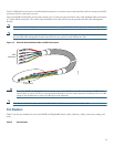
Console Port
The console port provides local administrative access to the router and its command-line interface (CLI).
273170