


24 Cisco 7000 and Cisco 7507 Chassis Replacement Instructions
Verifying the Installation
Verifying the Installation
This section provides instructions for first ensuring that all connections are secure and then for
restarting the system and verifying that it operates correctly. If the system does not start up and
operate as expected, the troubleshooting procedures in this section will help you isolate the cause of
the problem.
Checking Connections
Perform a final installation check of all components and cable connections as follows:
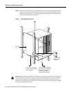
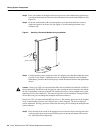
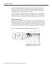
Step 1 Check the processor modules to make sure that each is inserted all the way into its slot, and
that both the top and bottom captive installation screws are tightened.
Step 2 Check the interface cable connections to the interface processors, and ensure that all cables
are fully seated in the ports and all strain relief systems are engaged.
Step 3 Ensure that the console cable is secured to the console port on the RP (in the Cisco 7000)
or the RSP2 (in the Cisco 7507), and that the console terminal is turned ON.
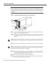
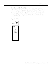
Step 4 Check the power supplies for the following:
• Each power supply is inserted all the way into its bay, and the captive installation screw
on each one is tightened.
• All power supply cables are inserted into the power supply and secured with the cable
retention clip.
Restarting the System
When you have checked all of the connection points, you will restart the system by turning on the
power supplies, and then verify that the system is operating properly by observing the LEDs on the
rear of the system.
Note The following warning is for units equipped with DC-input power supplies.
Warning After wiring the DC power supply, remove the tape from the circuit breaker switch handle
and reinstate power by moving the handle of the circuit breaker to the ON position. (For translations
of this safety warning, refer to the section “DC Power Connection Warning” on page 46.)
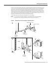
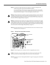
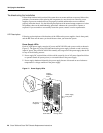
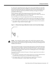
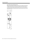
Step 1 Turn ON the lower power supply by turning the power supply switch clockwise one-quarter
turn. The lower power LED on the front of the chassis will go on.
Note If the power supply switch resists, the power supply is probably not fully inserted into the bay.
Turn the power switch off (fully counterclockwise to O), pull the power supply out of the bay about
two inches, then push the power supply firmly back into the slot. Do not slam the supply into the
slot; doing so can damage the connectors on the supply and the backplane. Tighten the captive
installation screw before proceeding.