


4 Cisco 7000 and Cisco 7507 Chassis Replacement Instructions
Product Overview
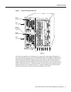
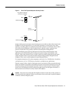
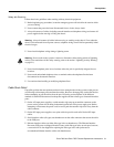
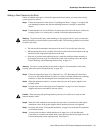
Figure 3 Power Supply Safety Interlocks
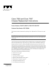
To the right of the power supply bays, the processor slots house the processor modules. In the Cisco
7000, the RP is always located in the far right slot (the RP slot), and the SP (or SSP) is always located
in the adjacent slot. The remaining five interface processor slots, numbered 0–4 from left to right,
support any combination of network interface types: serial, FDDI, Ethernet, and Token Ring, and so
forth.
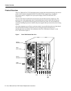
In the Cisco 7507, the RSP2 is always located in slot 2 or 3. The remaining six interface processor
slots, numbered 0 and 1 and 4 through 6, from left to right, support any combination of network
interface type.
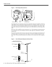
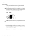
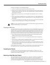
The processor modules slide into the slots and connect directly to the backplane. The backplane slots
are keyed to guides on each type of board. (See Figure 4 for the Cisco 7000 and Figure 5 for the
Cisco 7507.) The keys ensure that the processor modules can be installed only in their designated
slots.
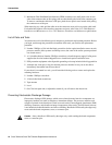
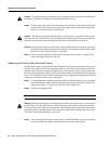
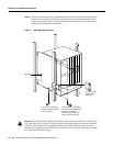
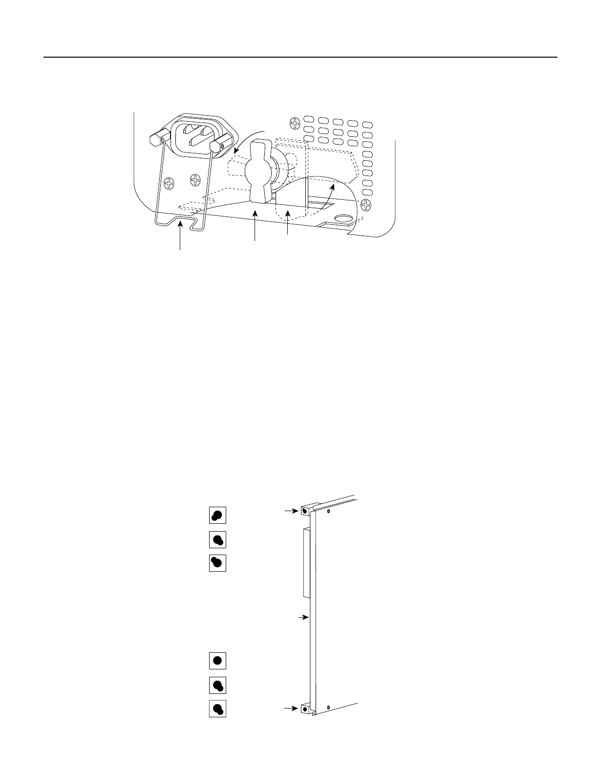
Figure 4 Cisco 7000 System Backplane Slot Key Guides
Safety interlock
switch
Locking device
in ON and
locked positions
I
O
H1315a
Cable-retention clip
Interface processor
slots 0–5
H3144
SSP (or SSP)
Key guides on interface
processors, RP and SP (or SSP)
Top
key guide
key guide
Rear of
processor card
Top
Bottom
RP
SSP (or SSP)
RP
Bottom
Interface processor
slots 0–5