


Cisco 7000 and Cisco 7507 Chassis Replacement Instructions 33
Verifying the Installation
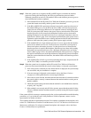
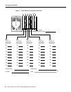
Step 7 When the system boot is complete, the RP (or RSP2) begins to initialize the interface
processors. During this initialization, the LEDs on each interface processor behave
differently (most flash on and off). The enabled LED on each interface processor goes on
when initialization has been completed.
• If the enabled LED on the SP (in the Cisco 7000) and all interface processors go on, the
system has booted successfully, and the system is now functional.
• If the RP (or RSP2) LEDs previously indicated a successful system boot, but none of
the enabled LEDs goes on, on the SP (in the Cisco 7000) or the interface processors,
suspect that one of them has shifted out of its backplane connector and hung the bus.
Turn all system power OFF, then use the ejector levers to ensure that the SP and each
interface processor is fully seated in the backplane. Push the top lever down while
pushing the bottom lever up until both levers are at a 90-degree orientation to the rear
of the chassis. (Refer to page 19 for a description and illustration of the ejector levers.)
Tighten the captive installation screws at the top and bottom ofthe SP and each interface
processor, then restart the system by turning ON all power supply switches.
• If the enabled LED on a single interface processor is not on, suspect that the interface
processor has shifted out of its slot. You do not have to turn off the system power to
remove and replace an interface processor. Use the ejector levers to ensure that the
interface processor is seated in the backplane. Push the top lever down while pushing
the bottom lever up until both levers are at a 90-degree orientation to the rear of the
chassis. (Refer to page 19 for a descriptionand illustration of the ejector levers.) Tighten
the captive installation screws at the top and bottom of the interface processor faceplate.
After the system reinitializes the interfaces, the enabled LED on the interface processor
should go on.
• If the enabled LEDs still fail to go on after performing these steps, suspect that the SP
(on the Cisco 7000) or an interface processor has failed.
Step 8 When the system boot is complete, and the SP (on the Cisco 7000) and all interface
processors have been initialized, the console screen displays a script and system banner.
• If all of the previous conditions are met and this banner is displayed, the system startup
was successful, and your installation is complete.
• If an error message is displayed on the terminal, refer to the Router Products
Configuration Guide publication for error message definitions.
• If the console screen is blank, check the terminal and ensure that it is turned on and that
the console cable is correctly connected between the terminal and the console port on
the RP (or RSP2).
• Check the terminal settings and ensure that the terminal is set for 9600 baud, 8 data bits,
no parity, and 2 stop bits.
• If the terminal is set correctly and still fails to operate, suspect that the terminal is faulty.
Connect a different terminal and then restart the system by turning ON all power supply
switches.
If the system still fails to start up or operate properly after you have performed these troubleshooting
procedures, or if you isolate the cause of the problem to a failed component, contact a service
representative for further assistance.
This completes thechassis replacement procedure. For complete systemhardware descriptions, refer
to the Cisco 7000 Hardware Installation and Maintenance or Cisco 7507 Hardware Installation and
Maintenance publication. For software command descriptions and examples, refer to the Router
Products Command Reference publication.