


Send documentation comments to mdsfeedback-doc@cisco.com.
14
Cisco MDS 9000 Family Port Analyzer Adapter Installation and Configuration Note
OL-9077-01
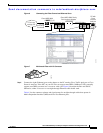
Installing the Port Analyzer Adapter
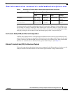
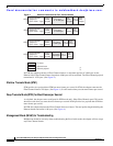
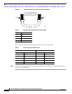
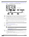
Figure 8 Cross-over Cable for Connection to Ethernet Switch
Table 5 lists the connector pinouts and signal names for the cross-over cable.
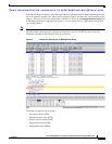
Step 5 Verify that the LED states match the configured settings once the adapter has powered on. (See Table 1
on page 6 for the LED states.)
P
in 1
1
30730
Pin
8
Pin 1 on one connector and
pin 8 on the other connector
should be the same color.
Table 4 Straight-Through Ethernet Cable Pinout (MDI)
RJ-45 Pin Signal
1Tx+
2Tx–
3Rx+
6Rx–
Table 5 Cross-over Ethernet Cable Pinout
Cable End A Cable End B
RJ-45 Pin Signal RJ-45 Pin Signal
1 Tx+ 3 Rx+
2 Tx– 6 Rx–
3Rx+ 1Tx+
6Rx– 2Tx–
4, 5, 7, 8 – 4, 5, 7, 8 –