


Send documentation comments to mdsfeedback-doc@cisco.com.
5
Cisco MDS 9000 Family Port Analyzer Adapter Installation and Configuration Note
OL-9077-01
Hardware Description
Hardware Description
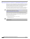
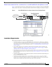
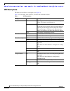
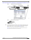
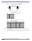
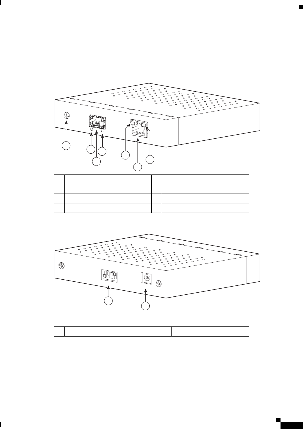
See the front view of the Port Analyzer Adapter in Figure 2and the rear view in Figure 3.
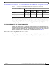
Figure 2 Cisco MDS 9000 Family Port Analyzer Adapter—Front View
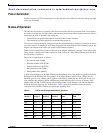
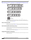
Figure 3 Cisco MDS 9000 Family Port Analyzer Adapter—Rear View
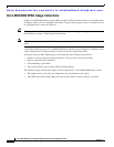
The four DIP switches, numbered 1 through 4 from left to right, are used to select the truncate mode as
described in the “Modes of Operation” section on page 7.
1 Status LED 5 Ethernet LED for 100 Mbps
2 Fibre Channel Link LED 6 Ethernet port
3 Fibre Channel port 7 Ethernet LED for 1 Gbps
4 Fibre Channel Speed LED
CISCO DS-FAA
LINK
SPEED
100M-
1G
STATUS
ETHERNET
1/2G FC
PORT ANALYZER ADAPTER
85677
1
2
3
4
5
6
7
1 DIP switches 2 12-VDC power input
CONFIGURATION
12VDC
85678
1 2 3 4
1
2