Card and Service Configuration 6-33
Adding a Frame Relay Connection
• CIR specifies the committed information rate. The range is 0–10000000 bps (although
the V.35 version supports a maximum of 8 Mbps sustained).
• chan_type is a number that identifies the channel type: 1=NIW. 2=transparent SIW.
3=SIW with translation. 4=FUNI. 5=frame forwarding.
• CAC enables connection admission control.
• Controller_type identifies the network control application. 1=PAR. 3=PNNI.
• specifies the mastership status of this end of the connection. 1=,aster. 2=slave.
• mastership indicates the mastership status for this end of the connection. 1=master.
2=slave.
• connID is the “remote” connection identifier from the slave end if you need to enter it
at the master end. See “Rules for Adding Connections” for an explanation. The
possible formats are:
— NodeName.SlotNo.PortNo.DlCI
— NodeName.SlotNo.PortNo.ControllerId.DlCI for Frame Relay end point
— NodeName.SlotNo.PortNo.VPI.VCI for ATM end point.
Where ControllerId can be 1(PAR),2(PNNI),3(TAG)
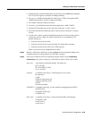
Step 2 Modify a connection as needed by executing cnfcon. See the command line Help or the
command reference for the parameters for individual card types.
Step 3 If necessary, modify the CLP and congestion indicator fields by using cnfchanmap:
cnfchanmap <chan_num> <chanType> <FECN/EFCI> <DE to CLP> <CLP to DE>
chan_num is the channel (connection) number. The ranges are:
2CT3, 16–4015
2T3, 2E3, HSSI, 16–2015
T1, E1, 16–1015
chanType is a number in the range 1–5 indicating the service type for
the connection.
1=NIW
2=SIW in transparent mode
3=SIW in translation mode
4=FUNI
5=frame forwarding
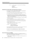
FECN/EFCI is a number in the range 1–2 that specifies the mapping between FECN
and EFCI fields.
1=map EFCI (SIW only)
2=set EFCI to 0
DE to CLP is a number in the range 1–3 that specifies the DE to CLP mapping.
1=map DE to CLP
2=set CLP to 0
3=set CLP to 1


