


3-5
Cisco ONS 15200 Product Description
78-13766-01
Chapter 3 Product Hardware
Physical Layout
Caution You must install the fan unit in a Release 1.0.1 shelf. Running the Release 1.0.1 shelf without the fan
unit will result in a unit that is not compliant to any specifications, nor is warranted or supported by
Cisco. In addition, such usage may result in equipment damage.
Caution Do not install the fan unit in a Release 1.0 shelf. Running the Release 1.0 shelf with a fan unit will
result in a unit that is not compliant to any specifications, nor is warranted or supported by Cisco. In
addition, such usage may result in equipment damage.
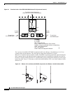
3.1.5 Fiber Organizer
The fiber organizer distributes the client fiber-optic cables to the ONS 15252 MCU CLIP modules.
Additionally, the fiber organizer provides tension relief for the client fiber-optic cables. You can also
install a fiber organizer between additional ONS 15252 MCUs or ONS 15201 SCUs located at a site. A
fiber organizer is always included with an ONS 15252 MCU.
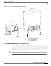
You can place the fiber organizer on the fan unit front. This placement does not interfere with fan unit
filter replacement.
3.2 Physical Layout
This section describes the physical configuration of the ONS 15252 MCU and ONS 15201 SCU.
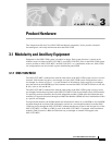
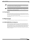
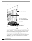
3.2.1 ONS 15252 MCU Physical Configuration
The ONS 15252 MCU physical configuration consists of a Network Control Board (NCB) module,
Network Adaptation modules (NAMs), a Communication Interface module (CIM), Client Layer
Interface Port (CLIP) modules, Hub Filter modules (HFMs), a pair of Line modules (LMs), and one
Bridge module (BM) (see Figure 3-4). A pair of Termination modules (TMs) replace the BM when all
optical signal channels or wavelengths are dropped at the ONS 15252 MCU. Additionally, when
multiple ONS 15252 MCUs are interconnected, Connection Module X (CMX) and/or Connection
Module Y (CMY) replace the BM. The type of connection module used depends on the specific ONS
15200 system configuration.