


3-7
Cisco ONS 15200 Product Description
78-13766-01
Chapter 3 Product Hardware
Physical Layout
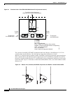
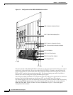
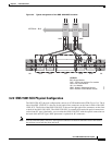
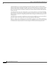
Figure 3-5 Typical arrangement of the ONS 15252 MCU modules
3.2.2 ONS 15201 SCU Physical Configuration
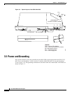
The ONS 15201 SCU physical configuration consists of a CLIP module and a CFM (Figure 3-6). The A
side of the ONS 15201 SCU is the two far-left optical line connectors on the front or back of the ONS
15201 SCU. The B side of the ONS 15201 SCU is the two far-right optical line connectors on the front
or back of the ONS 15201 SCU. The ONS 15201 SCU is normally delivered with optical connections
on the front (SC type). Optionally, you can order the ONS 15201 SCU with the optical connections on
the back of the unit (FC type). Back placement is optional for SC connectors.
Note You can order the ONS 15201 SCU with optical connectors located on either the front or the back of
the unit but not on both the front and back.
LM HFM HFM BM HFM HFM LM
NAMNAM
CLIP CLIP NCB
INTERNAL - BUS
LEGEND
BM - Bridge Module
CLIP - Client Line Interface Port module
HFM - Hub Filter Module
LM - Line Module
NAM - Network Adaptation Module
NCB - Network Control Board module
54638