


5-2
Cisco ONS 15200 Product Description
78-13766-01
Chapter 5 Module Descriptions
Communication Interface Module
optical signal to a specific International Telecommunication Union (ITU-T) G.692-compatible
wavelength. The CLIP module then transfers the converted optical signal to the DWDM side of the ONS
15200 network.
When the CLIP module receives the optical signal from the DWDM side of the ONS 15200 network, the
CLIP module converts the selected optical signal to the 1310 nm wavelength region and delivers it to
the client layer. If the ONS 15200 system is optically protected (that is, the optical signal is carried on
two routes), the CLIP module selects which optical signal to transfer to the client layer. You can install
a CLIP module in either the ONS 15252 Multichannel Unit (MCU) or the ONS 15201 Single-Channel
Unit (SCU).
When the CLIP modules are not installed, attach front covers for electromagnetic compatibility and
electromagnetic interference (EMC/EMI) precautions.
Release 1.1 provides a new CLIP module that incorporates both clocked (3R) and unclocked (2R) data
regeneration. You can set the mode of operation (2R or 3R) using the management interfaces. The new
2R/3R CLIP is fully compatible with the existing 3R CLIP. The 2R/3R CLIP is user configurable for
unprotected or fiber protected operation.
In addition, Release 1.1 provides two dispersion tolerances: 1800 ps/nm at 0 and 7 dBm, and 3000 ps/nm
at 0 dBm.
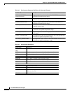
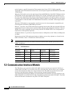
Restrictions exist for CLIP replacement based on whether you are using a plenum or a fan unit in the
ONS 15252 MCU. Table 5-1 identifies the CLIP restrictions.
Note CLIP replacement restrictions are related to mean time between failure (MTBF) performance and not
NEBS-2 compliance.
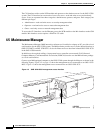
5.3 Communication Interface Module
The CIM allows you to extend the ONS 15252 MCU internal controller area network (CAN) bus to
another ONS 15252 MCU or to an ONS 15201 SCU. Extending the CAN bus allows you to configure
several network elements (NEs) into a larger functional unit. The CIM also provides the local craft
interface to the Maintenance Manager software package, and the Electronic Industry
Association/Telecommunication Industry Association (EIA/TIA) EIA/TIA-232 access interface to the
ONS 15252 MCU via an EIA/TIA-232 cable. The CIM is installed in the ONS 15252 MCU. The CIM
and the NCB module communicate using ONS 15252 MCU backplane.
Table 5-1 CLIP Restrictions
ONS 15252
Equipment
CLIP
Version
Maximum number
of CLIPs Restriction
Maximum
temperature
2U plenum 3.2 16 None 25°C (77°F)
2U plenum 3.2 4 Slots 1 – 440°C (104°F)
2U plenum 3.5 2 (3.5)/14 (3.2) Not adjacent 25°C (77°F)
2U plenum 3.5 3 Slots 1 – 340°C (104°F)
Fan unit 3.2 or 3.5 16 None None