


7 August 2003
Chapter 1 Cisco ONS 15530 Overview
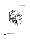
Cisco ONS 15530 Components
1-14
Cisco ONS 15530 Hardware Installation Guide
78-14228-02
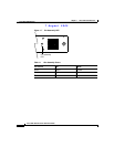
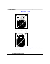
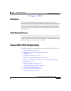
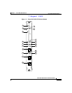
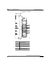
CPU Switch Module Ports, LEDs, and Switches
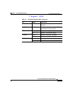
Table 1-2 lists the LEDs on the CPU switch module faceplate with a description
of the status indication.
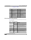
Callout Description Callout Description
1 Card status LED 10 HIST LED
2 Reset button 11 Cutoff LED
3 Standby LED 12 HIST CLR LED
4 Active LED 13 NME port
5 CompactFlash card slot 14 Link LED
6 Minor alarm LED 15 100 Mbps LED
7 Major alarm LED 16 Full-duplex LED
8 Critical alarm LED 17 Console port
9 Cutoff LED 18 Auxiliary port
Table 1-2 CPU Switch Module LEDs
LED Status Description
STATUS Green IOS is loaded and running.
Yellow Card is in the process of booting.
ACTIVE Green Module is the primary CPU switch
module, otherwise the LED is off.
STANDBY Green Module is in standby mode, otherwise the
LED is off.
ALARM LEDs
CRITICAL Red A system wide critical alarm exists.
MAJOR Yellow A system wide major alarm exists.
MINOR Yellow A system wide minor alarm exists.
HIST Yellow A system wide major or minor alarm has
occurred.