


7 August 2003
Chapter 1 Cisco ONS 15530 Overview
Cisco ONS 15530 Components
1-16
Cisco ONS 15530 Hardware Installation Guide
78-14228-02
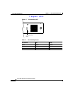
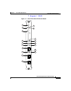
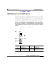
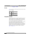
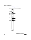
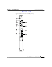
Connector Ports
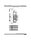
The front panel on the CPU switch module contains three ports with RJ-45
connectors (see Figure 1-11):
• Network Management Ethernet port (NME)—This Ethernet port connects the
CPU switch module to a 10/100BASE-T network management LAN.
• Console port (CON)—This asynchronous EIA/TIA-232 serial port connects
a terminal to the CPU switch module for local administrative access.
• Auxiliary port (AUX)—This asynchronous EIA/TIA-232 serial port connects
a modem to the CPU switch module for remote administrative access.
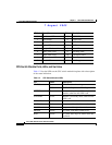
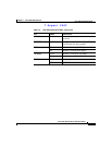
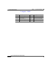
The RJ-45 connectors on the front panel of the CPU switch module have an extra
EMI shield and the signals going to them are filtered. Table 1-3 shows the pinouts
of the console and auxiliary ports.
CompactFlash Card Slot
A CompactFlash card slot (see Figure 1-11) can store the Cisco IOS image or a
system configuration file on a CompactFlash memory card. The system can also
boot from the software stored on the CompactFlash memory card.
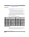
Table 1-3 Console and Auxiliary Port RJ-45 Pinout
Pin
# Console Auxiliary
Direction Function Direction Function
1 Output RTS Request To Send Output RTS Request To Send
2 Output DTR Data terminal ready Output DTR Data terminal ready
3 Output TxD Transmit data Output TxD Transmit data
4 N/A GND Ground N/A GND Ground
5 N/A GND Ground N/A GND Ground
6 Input RxD Receive data Input RxD Receive data
7 Input DSR Data set ready Input CD Carrier Detect
8 Input CTS Clear To Send Input CTS Clear To Send