


1-17
Cisco SN 5428-2 Storage Router Software Configuration Guide
OL-4691-01
Chapter 1 Before Configuring SN 5428-2 Storage Router Software
FCIP Overview
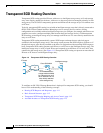
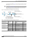
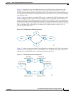
Figure 1-14 represents a basic, non-redundant structure of an FCIP network configuration. In this
example, an FC host or FC device connects to one or more Fibre Channel interfaces of each peer
SN 5428-2 Storage Router deployed for FCIP. Each SN 5428-2 connects to the IP network through one
of its Gigabit Ethernet interfaces. Through the IP network, each FCIP instance accesses its peer, thereby
connecting the SANs.
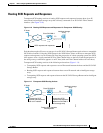
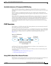
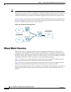
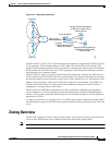
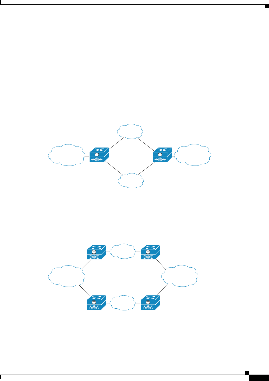
Figure 1-16 shows a slightly more complex FCIP network: a redundant WAN FCIP configuration. In this
example configuration, an FC host or FC device connects to one or more Fibre Channel interfaces of
each peer SN 5428-2 Storage Router deployed for FCIP, and each SN 5428-2 connects to two separate
IP networks through each of its Gigabit Ethernet interfaces. Through the IP network, each FCIP instance
accesses the peer storage router deployed for FCIP, connecting the SANs. In this configuration, IP A and
IP B are redundant paths, so that the loss of connectivity via either path does not cause a loss of
connectivity between the SANs.
Figure 1-16 FCIP Redundant WAN Configuration
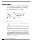
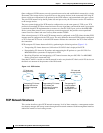
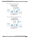
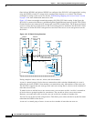
Figure 1-17 shows an even more reliable FCIP configuration, in which pairs of SN 5428-2s provide full
redundancy. In this configuration, loss of an SN 5428-2 or loss of connectivity through one of the IP
networks can be tolerated with no loss of connectivity between the SANs.
Figure 1-17 FCIP Fully Redundant Configuration
SN 5428-2
SN 5428-2
91533
SAN 1
SAN 2
IP
B
IP
A
IP
A
SN 5428-2
deployed for FCIP
SN 5428-2
deployed for FCIP
SN 5428-2
deployed for FCIP
SN 5428-2
deployed for FCIP
91009
FC hosts and
storage devices
FC hosts and
storage devices
SAN 1
SAN 2
IP
B