


1-23
Cisco SN 5428-2 Storage Router Software Configuration Guide
OL-4691-01
Chapter 1 Before Configuring SN 5428-2 Storage Router Software
Fibre Channel Interface Overview
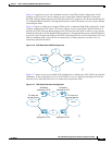
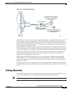
To apply zoning to a fabric, enable the appropriate zone set. When you enable (or “activate”) a zone set,
the system compiles zone sets of the same name from all SN 5428-2s and switches in the fabric, and then
redistributes this merged active zone set back to every SN 5428-2 and switch in the fabric. Therefore,
every SN 5428-2 and switch in the fabric will have identical active zone sets.
The SN 5428-2 supports multiple zone sets, but only one zone set can be active in the fabric at any given
time.
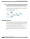
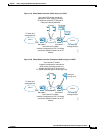
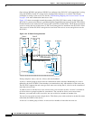
Each SN 5428-2, like other switches in the zoned FC switched fabric, has its own zoning database. The
zoning database is made up of all aliases, zones, and zone sets that have been created on the SN 5428-2
or received from other switches in the fabric. When you modify aliases, zone or zone sets, the changes
are immediately saved to the SN 5428-2 bootable configuration.
The Auto Save zoning configuration parameter controls whether zoning changes received from other
SN 5428-2s or switches in the fabric are automatically saved to the SN 5428-2s zoning database.
See Chapter 5, “Configuring Fibre Channel Interfaces,” for more information about configuring the
SN 5428-2 for FC fabric zoning.
Fibre Channel Interface Overview
The SN 5428-2 has an integrated switch component with Fibre Channel interfaces that support the
following port types: E_Port, F_Port, FL_Port, G_Port, GL_Port, TL_Port, and donor port. The storage
router supports a maximum of 7 FC Interswitch Link (ISL) hops.
The SN 5428-2 FC interfaces support GS-3 management server commands. This allows management of
the SN 5428-2 integrated switch component through the Fibre Channel interfaces (in-band
management). See the interface fc? ms-enable command in the Cisco SN 5400 Series Storage Router
Command Reference for more information about enabling the FC interfaces for GS-3 commands.
See Chapter 5, “Configuring Fibre Channel Interfaces,” for more information about configuring FC
ports.
Gigabit Ethernet Interface Overview
Each of the two 1-Gigabit Ethernet interfaces on the SN 5428-2 (GE 1 and GE 2) provide the following
capabilities:
• Multiple IP addresses per SCSI routing instance—allows IP hosts to connect to SCSI routing
instances via one or more IP addresses. Each Gigabit Ethernet interface can be configured with up
to 12 unique IP addresses, which provides a maximum of 24 unique IP addresses per SN 5428-2
Storage Router. If VLAN access is used, the maximum number of unique IP addresses per Gigabit
Ethernet interface increases to 16. This provides a maximum of 32 unique IP addresses per
SN 5428-2 Storage Router when configured with VLAN.
• Assignment of a secondary interface per SCSI routing instance—allows the same IP address to be
assigned to each Gigabit Ethernet interface; one interface is assigned as primary and one interface
is assigned as secondary. If the primary Gigabit Ethernet interface loses connection to the host and
if the secondary connection is assigned and still connected, the IP address moves to the secondary
Gigabit Ethernet interface, which then becomes active.
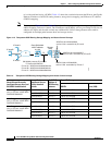
• Assignment as an interface to an FCIP peer—allows assignment of an IP address as a primary
Gigabit Ethernet interface between an FCIP instance and an FCIP peer. Each SN 5428-2 can be
configured with up to two FCIP instances, and each FCIP instance can be configured with one peer,
for a maximum of two FCIP peers per SN 5428-2 Storage Router when configured for FCIP.