


11
Cisco uBR10012 Universal Broadband Router Fan Assembly Module
OL-5093-01
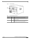
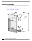
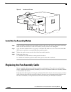
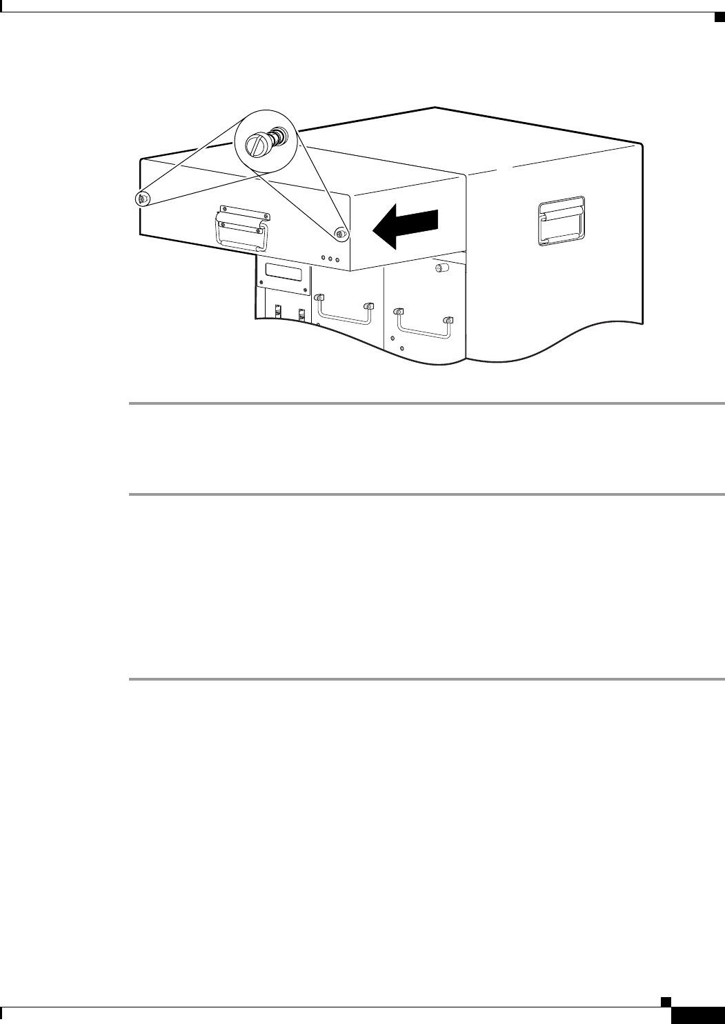
Figure 3 Locations of Screws
Install the Fan Assembly Module
Step 1 Using two hands, align the new fan assembly module in the slot in the chassis, and push it back firmly.
Make sure that the connectors on the can assembly securely connect to the backplane.
Step 2 Verify that the FANS OK LED is on (green). If the FANS OK LED is not on or if the FAN FAILURE
LED comes on (yellow), try reseating the fan assembly module.
Step 3 Tighten the captive screws on each side of the fan assembly module.
Step 4 Replace the front cover.
a. Slide the cover onto the four corner posts of the chassis.
b. Push down so that the posts are seated in the grooves above the cover holes.
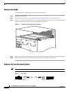
Replacing the Fan Assembly Cable
The fan assembly cable connects the fan assembly to the backplane. The cable is located inside the
chassis, underneath the fan assembly. Ordinarily the cable is not removed when a fan assembly module
is removed from the chassis.
Replacing a fan cable requires removing the cooling facilities of the chassis. It is not necessary to remove
power from the chassis for this procedure. However, because you are shutting down the fans that cool
the chassis and boards, it is important to have the new cable ready for immediate installation.
56293
CISCO
10000
CISCO