


13
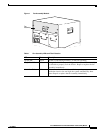
Cisco uBR10012 Universal Broadband Router Fan Assembly Module
OL-5093-01
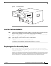
Step 1 Verify which connector goes in the bracket in the back of the chassis and which connector goes into the
front connector.
Step 2 Bend the cable in a “U” shape at both ends, to facilitate getting the cable into the rear bracket. See
Figure 4 on page 12.
Tip Use the existing cable as a template.
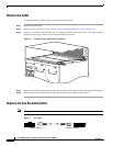
Step 3 Install the cable in the rear bracket.
Step 4 Make sure that the cable lays flat on the enclosure bottom so as not to restrict the movement of the cable
assembly as it is pushed back into the chassis.
Step 5 Connect the cable with the front connector.
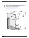
Step 6 Slide the fan assembly module back into the chassis. The module should slide smoothly back into the
chassis without interference with the cable.
Tip If the fan assembly module does not slide easily into the chassis, remove the module and check
the location of the cable. The cable should lay flat along the bottom of the fan assembly
enclosure.
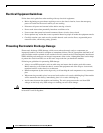
Troubleshooting the Fan Assembly
Check the following to help isolate a problem with the cooling system:
• When you start up the system, do the fans start operating?
When the fans are operating, you should be able to hear them. You should also be able to feel air
being drawn in at the bottom front and expelled at the top rear of the chassis.
–
If no, there is a problem with the fan or power. See the Cisco uBR10012 Series Hardware
Installation Guide, Troubleshooting the Power Subsystem, at the following URL:
http://www.cisco.com/univercd/cc/td/doc/product/cable/ubr10k/ubr10012/hig/u10ktrb.htm
–
If yes, continue with the next step.
• Is the System OK LED on the fan assembly module on (green) and are the other two LEDs (Single
Fan Failure and Multiple Fan Failure) off?
–
If yes, the system is operating normally.
–
If no, remove the fan assembly module and reinsert it. If this does not help, examine the LED
that is on. The Single Fan Failure LED indicates that one fan of the four has failed, but that the
system is still able to adequately cool the chassis; repair or replace the fan assembly module as
soon as possible. The Multiple Fan Failure LED indicates that more than one fan has failed, and
that the fan assembly module is no longer able to adequately cool the Cisco uBR10012 series
chassis. Replace the fan assembly module as soon as possible.