


12
Cisco uBR10012 Universal Broadband Router Fan Assembly Module
OL-5093-01
Remove the Cable
To replace the fan assembly cable, perform the following steps:
Step 1 Remove the front cover.
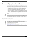
Step 2 Remove the fan assembly. See the “Remove the Fan Assembly Module” section on page 10.
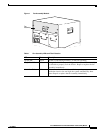
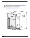
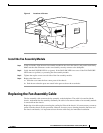
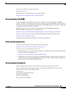
Step 3 See Figure 4. Note that the cable has two “U” shaped bends that allow the cable to curve back into the
brackets and fit snugly on the bottom of the fan module enclosure.
Figure 4 Location of Fan Cable Inside the Chassis
Step 4
Reach into the chassis and disconnect the cable from the rear bracket. Push the tabs on the bracket open.
Step 5 Disconnect the cable from the front connector and remove the cable from the chassis.
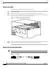
Replace the Fan Assembly Cable
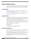
Note The cable has different connectors on each end.
Figure 5 Fan Cable
62337
CISCO
10000
ETHERNET
LINK
ACTIVITY
AUX
CISCO
10000
ETHER
NET
LINK
ACTIVITY
AUX
62338
Male connector Female connector