


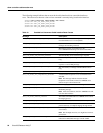
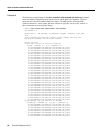
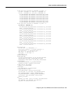
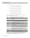
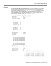
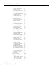
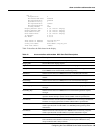
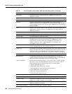
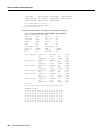

show controllers cable-modem mac
100
Cisco IOS Release 12.0(7)T
DS Frequency Downstream frequency acquired by the Cisco uBR900 series during its last
initialization sequence.
DS Symbol Rate Downstream frequency in symbols per second.
DS QAM Mode Downstream modulation scheme being used by the Cisco uBR900 series.
DS Search Frequency bands scanned by the Cisco uBR900 series when searching for a
downstream channel. The Cisco uBR900 series’ default frequency bands correspond
to the North American EIA CATV channel plan for 6 MHz channel slots between 90
MHz and 858 MHz.
US ID Identifier of the upstream channel to which this MAC management message refers.
This identifier is arbitrarily chosen by the CMTS and is only unique within the
MAC-sublayer domain.
US Frequency Transmission frequency used by the Cisco uBR900 series in the upstream direction.
US Power Level Transmit power level of the Cisco uBR900 series in the upstream direction.
US Symbol Rate Upstream frequency in symbols per second.
Ranging Offset Delay correction (in increments of 6.25 µs/64) applied by the Cisco uBR900 series to
the CMTS upstream frame time derived at the Cisco uBR900 series. Used to
synchronize the upstream transmissions in the time division multiple access
(TDMA) scheme, this value is roughly equal to the round-trip delay of the
Cisco uBR900 series from the CMTS.
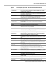
Mini-Slot Size Size T of the mini-slot for this upstream channel in units of the timebase tick of
6.25 µs. Allowable values are 2, 4, 8, 16, 32, 64, or 128.
Change Count Incremented by 1 by the CMTS whenever any of the values of this channel descriptor
change. If the value of this count in a sebsequent upstream channel descriptor (UCD)
remains the same, the Cisco uBR900 series can quickly decide that the remaining
fields have not changed, and may be able to disregard the remainder of the message.
Preamble Pattern Byte pattern used for the preamble.
Burst Descriptor:
Interval Usage Code
A compound type/length/value (TLV) encoding that defines, for each type of
upstream usage interval, the physical-layer characteristics that are to be used during
that interval. Each burst descriptor is given an identifying number.
Each upstream transmit burst belongs to a class which is given a number called the
IUC (interval usage code). Bandwidth MAP messages are used by IUC codes to
allocate upstream time slots. The following types are currently defined:
1. Request: bandwidth request slot
2. Request/Data: bandwidth request or data slot
3. Initial Maintenance: initial link registration contention slot
4. Station Maintenance: link keep-alive slot
5. Short Data Grant: short data burst slot
6. Long Data Grant: long data burst slot
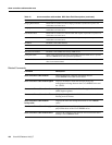
Modulation Type Upstream modulation format. (1 = QPSK; 2 = 16QAM)
Differential Encoding Indicates whether or not differential encoding is used. (1 = yes; 2 = no)
Preamble Length Length of the preamble in bits. This value must be an integral number of symbols—a
multiple of 2 for QPSK; a multiple of 4 for 16QAM.
FEC Error Correction Length of the forward error correction in bytes. The range is 0-10 bytes; a value of 0
implies no forward error correction.
FEC Codeword Info Bytes Number of information bytes in the FEC codeword.
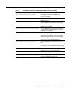
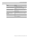
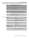
Table 12 show controllers cable-modem MAC State Field Descriptions (continued)
Field Description