


2-8
Cisco UCS C200 Server Installation and Service Guide
OL-20732-02
Chapter 2 Installing the Server
Installing the Server Into a Rack
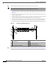
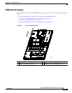
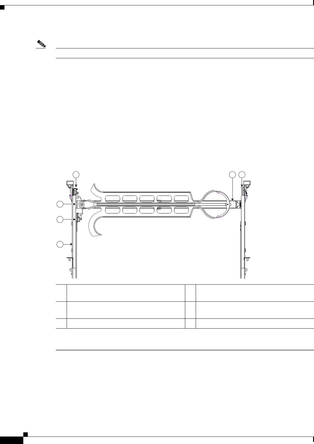
Step 4 Attach the (optional) cable management arm (CMA) to the rear of the slide rails:
Note The orientation in these instructions refers to a view from the front of the server.
a. Slide the plastic clip on the right end of the CMA length-adjustment slider (item 2) into the rear of
the right slide rail (item 1) until it clips onto the plastic retaining flange inside the slide rail. See
Figure 2-5.
b. Expand the CMA length-adjustment slider (item 2) until its left end aligns with the rear of the left
slide-rail assembly (item 3).
c. Slide the innermost CMA attachment clip (item 4) into the rear of the left slide rail (item 3) and clip
it onto the CMA flange that is on the mounting bracket that is attached to the server.
d. Attach the two-hole slotted bracket (item 5) that is on the left end of the CMA length-adjustment
slider to the left slide rail. Fit the two-hole slotted bracket over the two pegs inside the slide rail.
e. Attach the outermost CMA attachment clip (item 6) onto the CMA flange that is on the left slide rail.
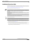
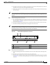
Figure 2-5 Attaching the Cable Management Arm
Step 5
Continue with the “Connecting and Powering On the Server (Standalone Mode)” section on page 2-9.
1 Rear of right slide rail (plastic retaining flange
is inside the rail)
4 Innermost CMA attachment clip
2 CMA length-adjustment slider 5 Two-hole slotted bracket on end of CMA
length-adjustment slider
3 Rear of left slide rail assembly 6 Outermost CMA attachment clip
126
3
5
4
195969