


19
Installing the Cisco WAE Inline Network Adapter
OL-12480-03
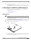
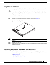
Installing Adapters in the WAE-7326 Appliance
Installing an Inline Network Adapter
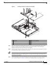
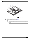
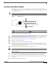
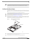
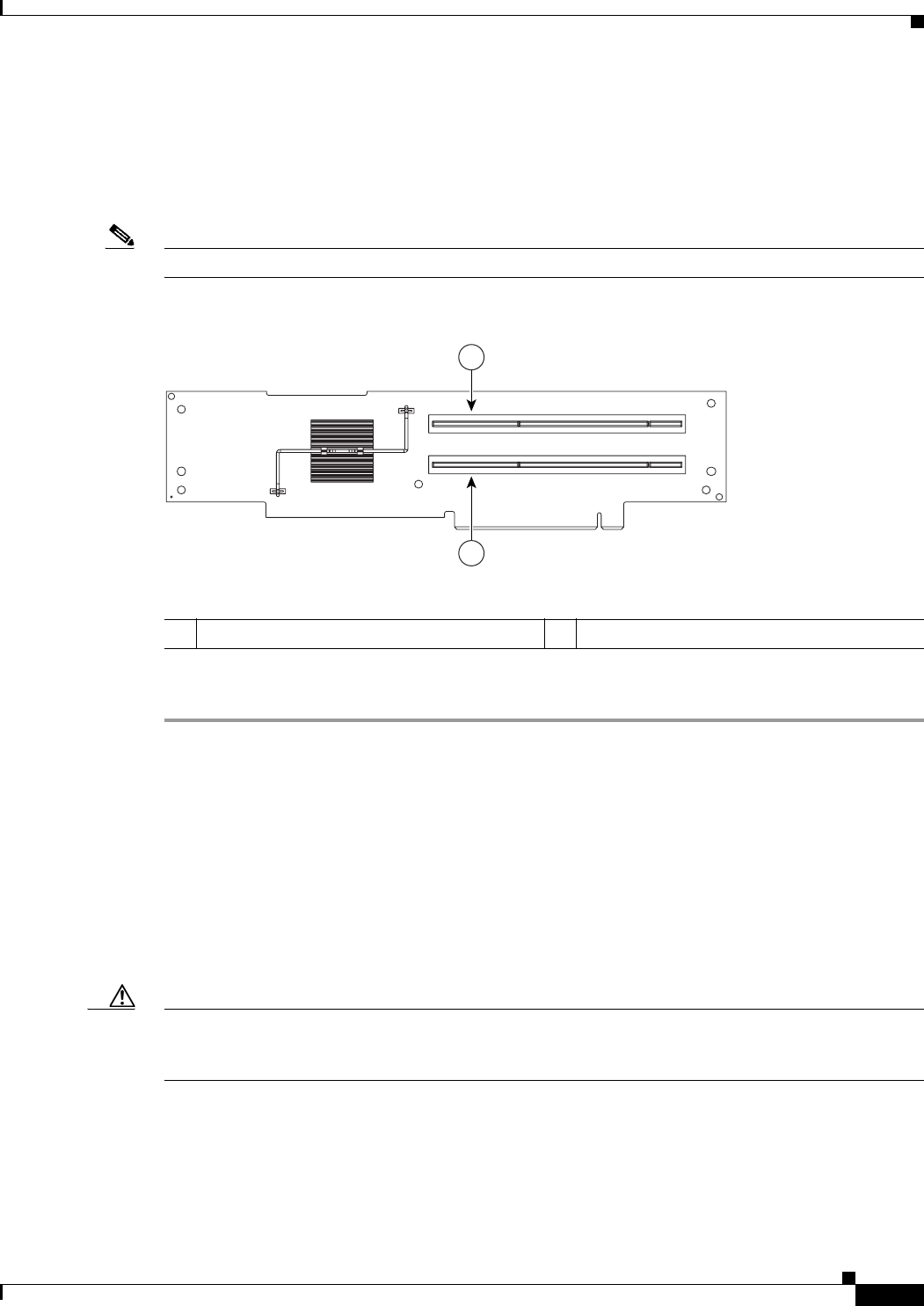
The WAE-7326 has connectors for up to four PCI adapters on the system board and PCI riser card. You
can install the inline network adapter in slot 3 (labeled 1 in Figure 12) or in slot 4 (labeled 2 Figure 12)
in on the PCI riser card.
Note The PCI riser card is located at J73 on the system board.
Figure 12 PCI-X Riser Card
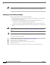
To install an inline network adapter, follow these steps:
Step 1 Review the information in the “Safety Guidelines” section on page 5.
Step 2 Power down the device and peripheral devices and disconnect all power cords and external cables.
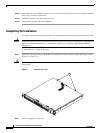
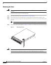
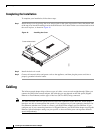
Step 3 Remove the cover. (See the “Removing the Cover” section on page 18.)
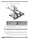
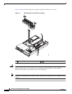
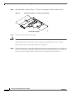
Step 4 Remove the PCI riser card assembly.
Step 5 Slide the expansion-slot cover out of the PCI riser card cage.
Step 6 Touch the static-protective package that contains the adapter to any unpainted metal surface on the
device, and then remove the adapter from the static-protective package. Avoid touching the components
and gold-plated edge connectors on the adapter.
Step 7 Place the adapter, component-side up, on a flat, static-protective surface.
Caution When you install an adapter in the device, be sure that it is completely and correctly seated in the PCI
expansion slot before you power up the device. Incomplete insertion might cause damage to the system
board or the adapter.
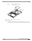
Step 8 To install the adapter, carefully grasp the adapter by its top edge or upper corners, align it with the
expansion slot in the riser card assembly, and then press the adapter firmly into the expansion slot.
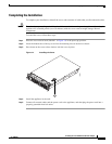
Step 9 Reinstall the riser card. Make sure that the riser card is fully seated in the riser card connectors on the
system board.
Step 10 Connect any needed cables to the adapter.
1 PCI-X slot 3, 64 bit 3.3 V 133 MHz (PCI 3) 2 PCI-X slot 4, 64 bit 3.3 V 133 MHz (PCI 4)
137707
1
2