


— 14 —
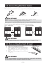
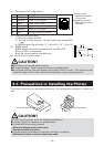
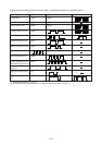
(1) Connector Pin Configuration
No. Signal Function
1FG Frame Ground
2 DRAWER 1 Drawer 1 drive signal
3 DRSW Drawer switch input
4 VDR Drawer drive power supply
5 DRAWER 2 Drawer 2 drive signal
6 GND Common ground on circuits
61
Connector used:
TM5RJ3-66 (Hirose)
or equivalent
Applicable connector:
TM3P-66P (Hirose) or
equivalent
VDR
1
2
3
4
5
6
VDR
5V
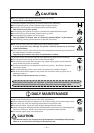
CAUTION!
■ No output is produced while printing.
■ The cash drawers 1 and 2 cannot be driven simultaneously.
■ A solenoid used for the cash drawer should be of 24 Ω or more. The output current
should be kept at 1A or less; otherwise, breakdown or burning could occur.
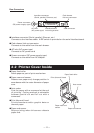
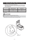
CAUTION!
DO NOT use the printer under the following conditions.
■ A state subject to vibration or unstable state.
■ A state with this product slanted.
• Otherwise dropping may cause injury.
• Poor print quality may occur.
■ A state where this product is installed vertically or sidelong.
• Malfunction, failure, or electric shock may result.
Horizontal position
Vertical position
(2) Electrical characteristics
1) Driving voltage: 24 VDC
2) Driving current: Approx. 1A max. (shall not exceed 510
ms.)
3) DRSW signal: Signal levels: “L” = 0 to 0.5 V, “H” = 3 to 5 V
(3) DRSW signal
DRSW signal status can be tested with the DLE+EOT,
GS+a, or GS+r command or
at pin 34 on the parallel interface port.
(4) Drive Circuit (printer side)
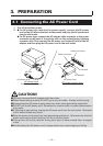
3.4 Precautions in Installing the Printer
The printer must only be operated horizontally. Do not operate vertically or install on a
wall.