


CITIZEN 38
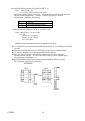
(20) Enabling/Disabling Panel Switch (ESC c 5 n)
Code : [1B]h + [63]h + [35]h + n
* {0 ≤ n ≤ FF} Data is described in Hex code.
Selecting the LF switch valid/invalid.
l "n" is valid only in the lowest bit (n0).
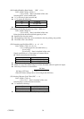
l "n" bit means the followings.
N0 Condition
0 LF SW valid.
1 LF SW invalid.
l The initial value of n is "0".
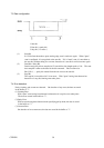
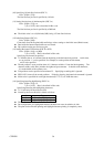
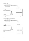
(21) Printing and Feeding the paper by n lines (ESC d n)
Code : [1B]h + [64]h + n
* {0 ≤ n ≤ FF} Data is described in Hex code.
Prints data inside the buffer and feeds paper by n lines.
l Specified line does not remain.
l The beginning of the line is to be considered as the next printing start position.
l The initial value is not defined.
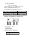
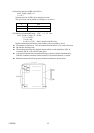
(22) Generating specified Pulse (ESC p m n1 n2)
Code : [1B]h + [70]h + m + n + n2
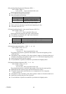
* {m = connector pin No. (See table below.)}
{0 ≤ n1 ≤ FF}
{0 ≤ n2 ≤ FF} Data is described in Hex code.
Signals specified by n1, n2 are output to Connector Pin m.
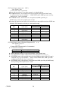
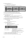
l Bit m (m0) means the followings.
m0 Condition
0 Drawer kick No. 2 pin
1 Drawer kick No. 5 pin
l ON time is considered as n1 x 2ms and OFF time as n2 x 2ms.
l When m is out of the defined range, n1, n2 are discarded, where no signals are output.
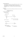
l Drive duty of Drawer is shown below:
ON time
ON time + OFF time ≤ 0.2
(Take OFF time as being 4 times or more longer than ON time.)
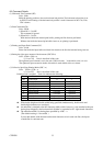
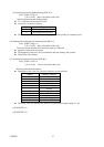
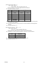
(23) Selecting Character Code Table (ESC t n)
Code : [1B]h + [74]h + n
* {0 ≤ n ≤ 1} Data is described in Hex code.
Selecting Page n on the character code table:
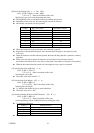
l "n" means the followings.
n (Hex) Condition
0 IBM Character #2
1 Japanese Character
l The initial value of n is specified by Jumper setting (J1 - J3).