—21—
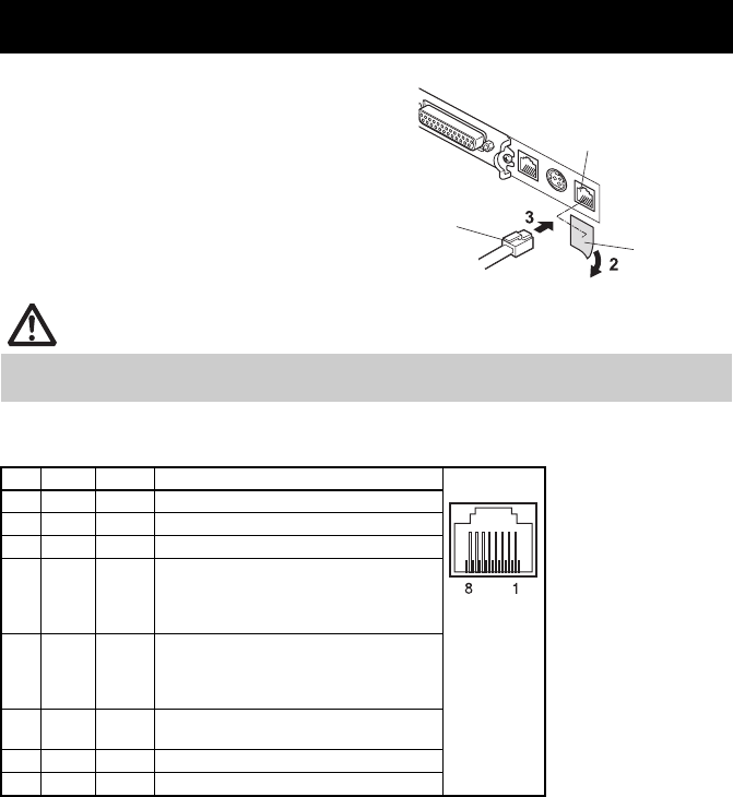
1. Turn off the power.
2. Remove the protective seal from
the external device connecter.
3. Confirm the orientation of the
external device cable connecter
and connect it to the external
device connecter at the back of the
printer.
(1) Connector pin configuration
Transmission to external devices done at 19200 bps, 8-bit, no parity.
3.4 Connecting an External Device
CAUTION
Use only the specified external device cable to connect to the external device connector
(do not use phone, LAN, or USB cables).
No. Signal I/O Function
1 FG — Frame ground Connector used: RJ-45
Applicable connector:
RJ-45
2 TXD Output Data sent to printer
3 RXD Input Data received from external device
4 DSR Input Indicates that the printer can receive
data.
MARK: Printer cannot receive
SPACE:Printer can receive
5 DTR Output Indicates that the external device can
receive.
MARK: External device cannot receive
SPACE:External device can receive
6 SG — Signal ground (common ground on
circuits)
7 PS — Power supply terminal (24 VDC)
8 PG — Flyback line for power supply
External device
connector
Protective
seal
External device cable
connector


