


iDP-3420/3421/3423 User’s Manual
53 CITIZEN
1
11
11
11
1.
..
.D
DD
DR
RR
RA
AA
AW
WW
WE
EE
ER
R R
R K
KK
KI
II
IC
CC
CK
KK
K-
--
-O
OO
OU
UU
UT
T T
T C
CC
CO
OO
ONN
NNNN
NNE
EE
EC
CC
CT
TT
TO
OO
OR
RR
R
1
11
11
11
1.
..
.1
11
1S
SS
Sp
pp
pe
ee
ec
cc
ci
ii
if
ff
fi
ii
ic
cc
ca
aa
at
tt
ti
ii
io
oo
on
nn
ns
s s
s o
oo
of
f f
f D
DD
Dr
rr
ra
aa
aw
ww
we
ee
er
r r
r K
KK
Ki
ii
ic
cc
ck
kk
k-
--
-O
OO
Ou
uu
ut
t t
t C
CC
Co
oo
onn
nnnn
nne
ee
ec
cc
ct
tt
to
oo
or
rr
r
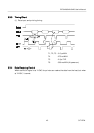
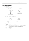
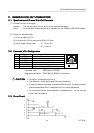
(1) Drawer kick-out drive signal
Parallel ----- Can be learned at the no. 34 pin of the interface connector
Serial ----- Provided with a command to learn the status in the STAR and ESC/POS modes.
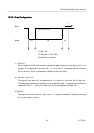
(2) Electrical characteristics
1) Drive voltage: 24 V DC
2) Drive current: 0.8 A at maximum (Within 510 ms)
3) Switch signal: Signal level "L" = 0 to 0.5 V
"H" = 3 to 5 V
1
11
11
11
1.
..
.2
22
2C
CC
Co
oo
onn
nnnn
nne
ee
ec
cc
ct
tt
to
oo
or
rr
r'
''
's
s s
s P
PP
Pi
ii
in
n n
n C
CC
Co
oo
on
nn
nf
ff
fi
ii
ig
gg
gu
uu
ur
rr
ra
aa
at
tt
ti
ii
io
oo
on
nn
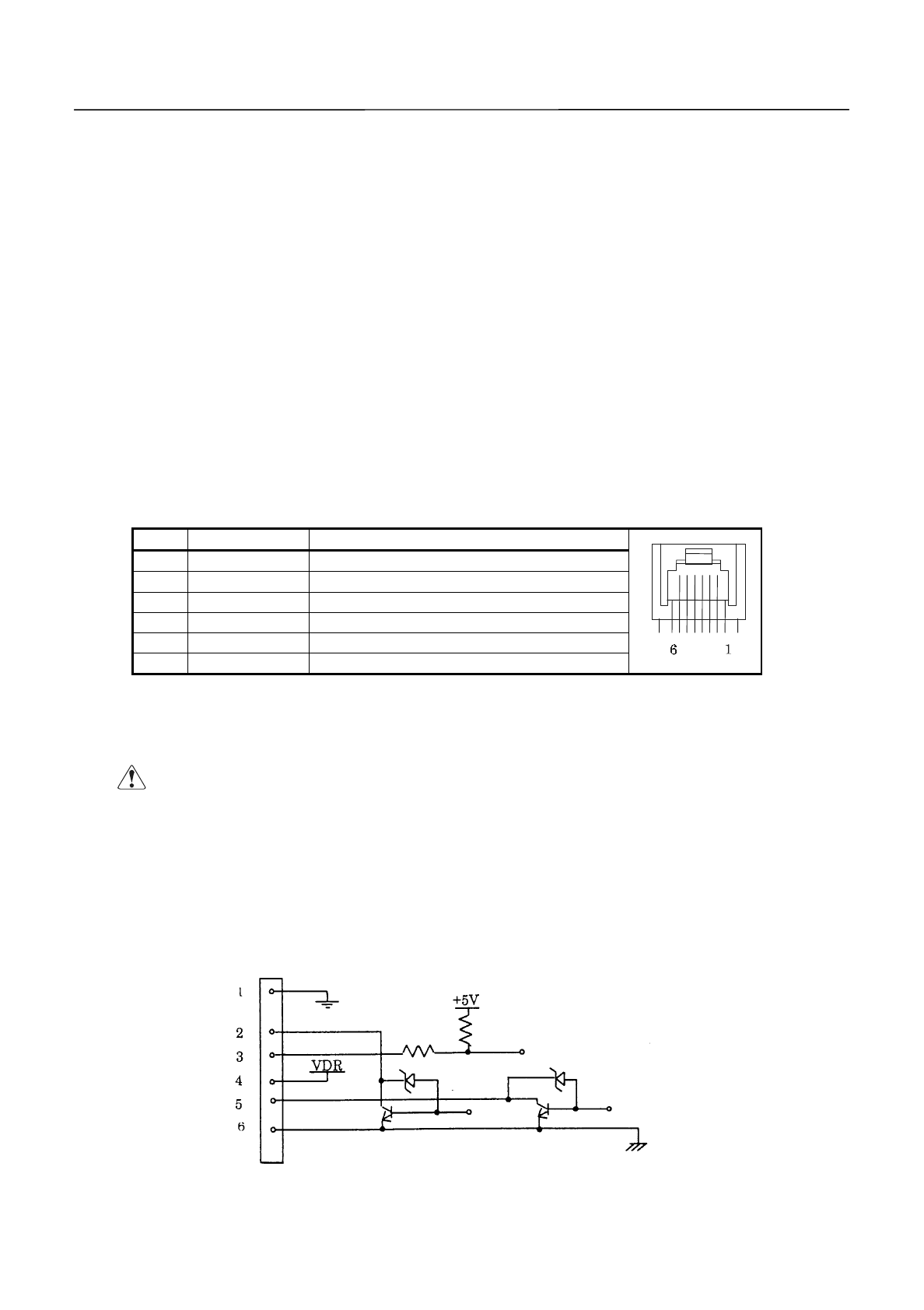
n
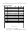
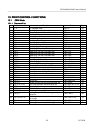
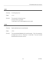
No. Signal Function
1 FG Frame Ground
2 DRAWER 1 Drawer 1 drive signal
3 DRSW Drawer switch input
4 VDR Drawer drive power
5 DRAWER 2 Drawer 2 drive signal
6 GND Common ground on the circuit
Connector used : TM5RJ3-66 (HIROSE)
Applicable connector : TM3P-66P (HIROSE) or equivalent
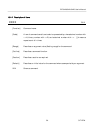
C
CC
CA
AA
AU
UU
UT
TT
TI
II
IO
OO
ON
NN
N
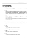
:
·
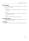
No output is made while printing.
·
The drawers 1 and 2 cannot be driven simultaneously.
·
A solenoid used for the drawer should be of 36
W
or more. An output current
should be kept below 0.8 A. Use beyond this limit cannot be assured.
·
This connector cannot be connected to a telephone line. Do not connect
other than the solenoid.
1
11
11
11
1.
..
.3
33
3D
DD
Dr
rr
ri
ii
iv
vv
ve
e e
e C
CC
Ci
ii
ir
rr
rc
cc
cu
uu
ui
ii
it
tt
t