


iDP3420/3421/3423 User’s Manual
38 CITIZEN
11. DRAWER KICK-OUT CONNECTOR
11.1 Specifications of Drawer Kick-Out Connector
(1) Drawer kick-out drive signal
Parallel ----- Can be learned at the no. 34 pin of the interface connector
Serial ----- Provided with a command to learn the status in the Star and ESC/POS modes.
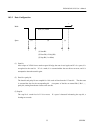
(2) Electrical characteristics
1) Drive voltage: 24 V DC
2) Drive current: 0.8 A at maximum (Within 510 ms)
3) Switch signal: Signal level "L" = 0 to 0.5 V
"H" = 3 to 5 V
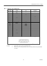
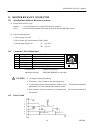
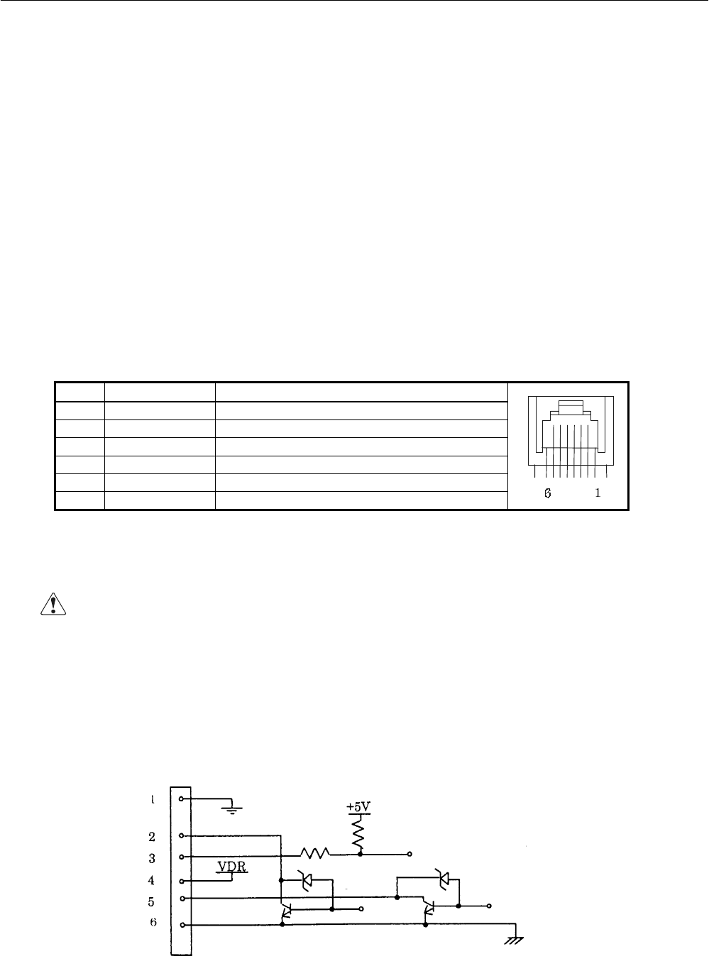
11.2 Connector's Pin Configuration
No. Signal Function
1 FG Frame Ground
2 DRAWER 1 Drawer 1 drive signal
3 DRSW Drawer switch input
4 VDR Drawer drive power
5 DRAWER 2 Drawer 2 drive signal
6 GND Common ground on the circuit
Connector used : TM5RJ3-66 (HIROSE)
Applicable connector : TM3P-66P (HIROSE) or equivalent
CAUTION : • No output is made while printing.
• The drawers 1 and 2 cannot be driven simultaneously.
• A solenoid used for the drawer should be of 36Ω or more. An output current should be
kept below 0.8 A. Use beyond this limit cannot be assured.
• This connector cannot be connected to a telephone line. Do not connect other than
the solenoid.
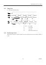
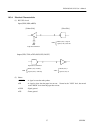
11.3 Drive Circuit