


3-4 Compaq 2000 Series UPS Operation and Reference Guide
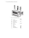
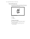
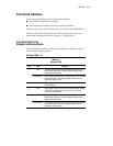
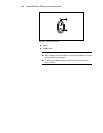
The front panel includes the following controls and indicators:
1
2
3
4
5
6
7
8
9
10
11
12
13
14
15
16
17
18
19
Figure 3-1. The front panel LED display and controls
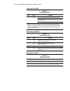
Symbol
–
AC Input level Power cord
Site Wiring Fault indicator
–
Battery Charge level Battery
Battery Service indicator
–
Load level Load devices
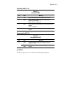
Communications
ON LED
ON button
STANDBY button
TEST/ALARM RESET button