


Removal and replacement procedures 4–39
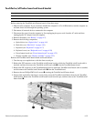
When replacing the system board, be sure that the following components are removed from the defective system
board and installed on the replacement system board:
■ RTC battery (see “RTC battery” on page 4-12)
■ Memory module (see “Memory module” on page 4-13)
■ WLAN module (see “WLAN module” on page 4-15)
■ Fan/heat sink assembly (see “Fan/heat sink assembly” on page 4-41)
■ Processor (see “Processor” on page 4-44)
Remove the system board:
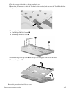
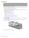
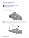
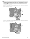
1. Disconnect the USB board cable 1 from its mounting clip in the base enclosure.
2. Disconnect the Bluetooth cable 2 from the system board.
3. Disconnect the RJ-11 cable 3 from the system board.
4. Disconnect the audio cable 4 from the system board.
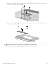
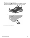
Ä
CAUTION: Do not attempt to disconnect the optical extension board before removing the system board. Otherwise, you will
damage the locator pin on the optical extension board.
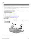
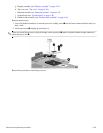
5. Remove the four Phillips PM2.5x6.0 screws 1 that secure the system board
6. Remove the two Phillips PM2.5x5.0 screws 2 that secure the optical extension board.