


Removal and replacement procedures 4–42
✎
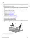
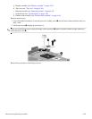
Due to the adhesive quality of the thermal material located between the fan/heat sink assembly and system board
components, you may need to move the fan/heat sink assembly from side to side to detach the assembly.
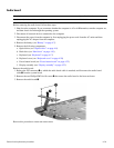
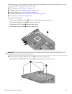
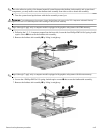
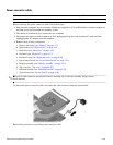
3. Turn the system board upside down with the fan assembly toward you.
Å
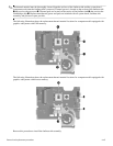
WARNING: To avoid damage to the processor, loosen the fan/heat sink screws in the 1-2-3-4 sequence indicated. Likewise,
tighten the screws in the same sequence when installing the fan/heat sink assembly.
✎
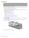
Steps 4 through 5 apply only to computer models equipped with graphics subsystems with UMA memory.
4. Following the 1, 2, 3, 4 sequence stamped into the heat sink, loosen the four Phillips PM2.0x10.0 spring-loaded
captive screws 1 that secure the fan/heat sink assembly.
5. Remove the fan/heat sink assembly 2 by lifting it straight up.
✎
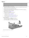
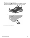
Steps 6 through 7 apply only to computer models equipped with graphics subsystems with discrete memory.
6. Loosen the 4 Phillips PM2.0x11.0 spring-loaded captive screws 1 that secure the fan/heatsink assembly.
7. Remove the fan/heat sink assembly 2 by lifting it straight up.