E-8
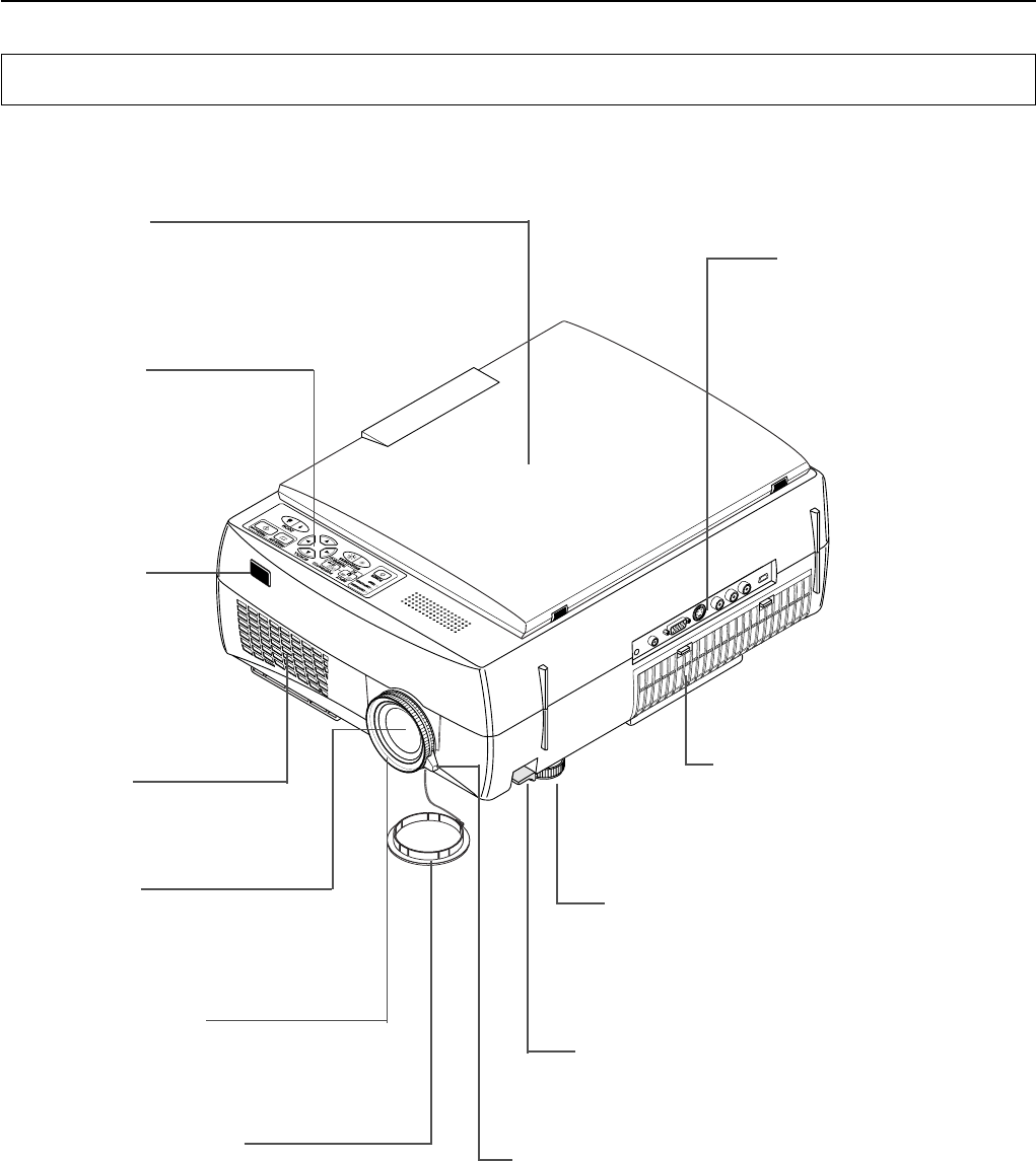
Remote control
IR sensor
Lens cap
Focus adjustment ring
Turn this to adjust the focus.
See Page E-22.
Projection lens
The image is projected from here.
* Be sure to remove the lens cap
before projecting.
Zoom lever
Turn this to adjust the screen size. See Page E-22.
Document cover
The document or printed material to be read is
placed under this cover.
See Page E-30.
Operation panel
The buttons used for regular op-
eration are located here. See
Page E-11.
Air intake vent (Air filter)
Air is drawn into the projector from here.
There is an air filter to prevent dust from
entering the inside of the projector. See
Page E-45.
Tilt adjustment lever
Press here to adjust the tilt foot. See Page E-22.
Tilt foot
This foot is used to adjust the vertical angle of the
projection as well as the left-right balance. Turning it
to the left extends it and turning it to the right short-
ens it. See Page E-22.
Input connector panel
The connectors for the personal
computer, video, and other con-
nections are located here.
See Page E-10.
Exhaust vents
Air is discharged from here.
A Check of the Supplied Items and the Names of the Parts
Names and Functions of the Parts (Projector)


