


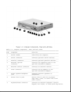
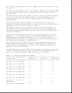

LTE 5250 10.4 in SVGA CTFT 2-3 2-3 2-3
LTE 5380 12.1 in 1024 x 768
CTFT 2-3 1-2 1-2
LTE 5400 12.1 in 1024 x 768
CTFT 2-3 2-3 2-3
===========================================================================
The power-on password jumper is also located on the processor board. To
erase the power-on password, set jumper JP1 to pins 1 and 2; set JP1 to
pins 2 and 3 for normal operation. See Chapter 2 for more details.
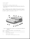
To remove and replace the processor board, you must first remove the CPU
cover, EMI shield, keyboard, and display unit. The processor board is
secured in place with two screws and is connected to the system board with
two connectors.
System Board
There are three system boards for the computer: one to support the 75 MHz,
90 MHz and 120 MHz processors (LTE 5000, LTE 5100, and LTE 5200); one to
support the 120 MHz, 100MHz, and 133 MHz processors (LTE 5280, LTE 5300,
LTE 5150, and LTE 5250); and one to support the 133 MHz processor (LTE
5380) and 150MHz processor (LTE 5400). The system board supports the
following:
o System ROM (BIOS)
o Graphics subsystem
o Audio subsystem
o PC Card subsystem
o Diskette drive controller
o RS-232 and IrDA serial ports
o IDE interface
o Fan connector
o I/O connectors
The firmware components for the computer include:
o System BIOS for the OPTi Viper Notebook chip set
o ROM-based setup
o MAXIMIZER Power Management for OPTi Viper
o APM 1.1 BIOS
o Plug and Play BIOS