


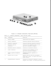

The system unit contains the following field replaceable units:
o CPU cover
o Internal microphone
o Status panel
o Processor board
o Power board
o Cooling fan
o System board
o Memory expansion board (optional)
o Keyboard assembly
o Auxiliary battery
o Miscellaneous plastic parts
CPU Cover
The CPU cover is located above the keyboard and is secured in place with
three screws on the rear panel of the system unit. Tabs on the front edge
of the CPU cover engage slots across the top edge of the keyboard panel.
The CPU cover contains the actuators for the following:
o Power switch
o Standby (Suspend) button
o Display switch
The CPU cover with all switch actuators installed is available as a field
replaceable unit. The switch actuators are also available as field
replaceable units.
The power switch actuator and spring and the standby (suspend) button
actuator and spring are removed by squeezing the actuator tabs on the
underside of the CPU cover and pushing the buttons out of their mounting
hole. The display switch actuator simply snaps out of its mounting hole
from the underside of the CPU cover.
The CPU cover must be removed to service any of the above described switch
actuators. The cover also must be removed to disconnect any of the display
unit cables from the system unit, to remove the display unit, to service
the status panel, and to remove the keyboard assembly.
Internal Microphone
The internal microphone is supported by the audio subsystem and connects