


Index
Maintenance and Service Guide Index–3
G
grounding equipment and
methods
4–6
H
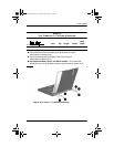
hard drive
location
1–35, 1–37, 1–39
OS loading problems
2–20
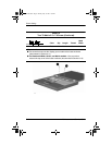
removing
5–8
security screw
1–39
spare part numbers
3–13,
3–19, 5–8
specifications
6–4
hard drive bezel
illustrated
3–16
removing
5–10
hard drive security screw
1–41
headphone jack
location
1–33
pin assignments
A–1
heat sink
removing
5–46
spare part number
3–11,
5–46
I
I/O address specifications
6–13
illustrated parts catalog
3–1
infrared port
1–33
interrupt specifications
6–12
Iomega Zip drive, spare part
number
3–15, 3–21, 5–6
K
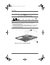
keyboard
components
1–44
removing
5–17
spare part numbers
3–3,
3–5, 5–17
troubleshooting
2–28
keyboard connector
location
1–34, 1–37
pin assignments
A–2
L
left side components 1–34,
1–36
Logo Kit, spare part number
3–22
M
mass storage devices 3–18
Media Bay
1–40
location
1–33, 1–38
release latch
1–38
Media Bay device
removing
5–7
spare part numbers
3–15,
3–21, 5–6
Media Bay release latch
1–40,
5–7
Media Bay space saver
3–16
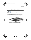
memory expansion board
removing
5–22
spare part numbers
3–9,
5–22
memory expansion
compartment cover
illustrated
3–16
location
1–41
279362-003.book Page 3 Monday, May 19, 2003 1:28 PM