


Removal and Replacement Procedures
Maintenance and Service Guide 5–55
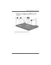
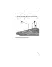
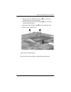
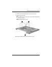
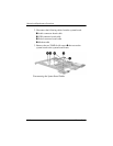
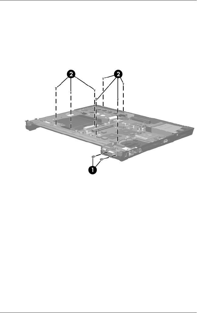
5. Position the notebook with the rear panel toward you.
6. Remove the following:
1 Two HM5.0×10.0 screw locks on each side of the external
monitor connector
2 Seven T8M2.0×6.0 screws
Removing the System Board Screws and Screw Locks