


5–60 Maintenance and Service Guide
Removal and Replacement Procedures
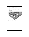
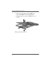
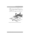
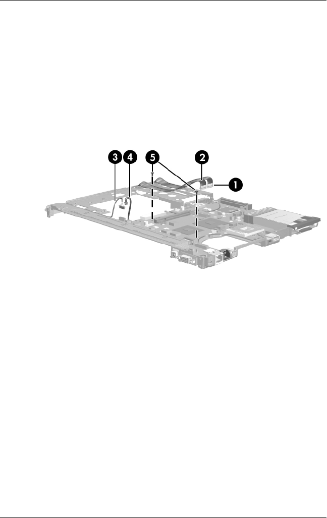
2. Disconnect the following cables from the system board:
1 Audio connector board cable
2 USB connector board cable
3 Serial connector board cable
4 Modem cable
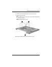
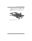
3. Remove the two T8M2.0×4.0 screws 5 that secure the
system board to the system board frame.
Disconnecting the System Board Cables