


QuickSpecs
ProLiant BL20p and p-Class system
DA-11411 Canada — Version 1 — August 26, 2002
22
Technical Specifications
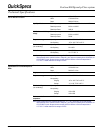
Voltage Nominal input voltage -48 VDC Operating and Performance
Specifications for Facility DC
Operating voltage range
-48VDC ± 10% or -43.2 VDC to -52.8 VDC
Max Input voltage slew rate 0.5V/uS
Redundant feed voltages*
(A & B)
*A and B feeds must differ by no more than
5VDC during steady state operation
Ripple/Noise 480 mV PARD**
Overshoot Must remain within regulation limits on all feeds
during startup or shutdown
Voltage transients Must not exceed -60 VDC
Current Max steady state input current 62.5A per server blade enclosure installed at
-48VDC
Max steady state current per
feed/total
Power bus boxes 70 A/70A
Mini bus bars 210 A/210A
Scalable bus bars 210 A/350A or equivalent of 175A per feed*
In-rush current Must support up to 2X the maximum operating current per server blade
enclosure (125 A) for up to 1.0 mS
Input over-current Customer provided fusing for facility DC feeds that protects the system from
catastrophic over-current within 20 uS. Fuse should sustain all in-rush and
operating currents.
Max Input Current Slew Rate 1A/uS
Max Rated Power 3000W per server blade enclosure
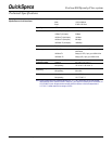
Connections and Cables
Compaq provided facility DC cable connection kit:
• The facility DC connection kit supports the connection of up to four -
48VDC, RETURN pairs and ground.
The power cable assemblies consist of 1/0AWG, colour-coded, flexible cable
rated at 105° C, terminated with bus mating connectors at one end and
unterminated at the other end. The cable length provided enables the customer
to route to a fuse panel within or adjacent to the rack.
Note: *All systems support redundant A and B feeds. Scalable bus bars support dual A and dual B feeds.
** Periodic and random noise (PARD). Maximum allowable peak-to-peak ripple and noise (as measured at
the load on any output channel). The ripple and noise is measured over a 20 Hz to 100 MHz frequency
band. A resistive load (non-electronic) is used for this measurement. Each output is by-passed to return
by a 10uF tantalum capacitor with an ESR less than 100 milli-Ohms in parallel with a 0.47 uF ceramic
capacitor, at the point of load. The load cable is 12 feet of twisted wire capable of carrying the current.
The printed wiring board assembly is installed in its enclosure for this measurement, or the measurement
leads are properly shielded with Earth grounds applied to the insert.