


BlueStorm Installation Guide, Connect Tech Inc.
12 Revision 0.10
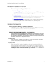
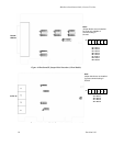
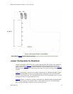
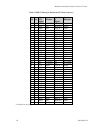
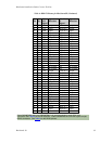
Figure 9 illustrates the jumper configurations for selecting +5V power or +12V power.
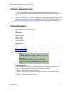
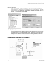
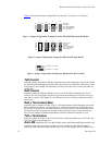
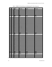
Figure 7: Jumper Configuration Example for 4 Port RS-422/485 BlueStorm/LP Models
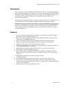
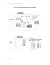
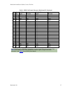
Figure 8: Jumper Configuration Example for BlueStorm/SP Opto Models
Figure 9: Jumper Configuration Examples for BlueStorm/SP RJ-11 Models
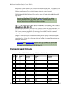
TxD Control
Install this jumper to enable the RS-485 transmitter only when sending data. This mode is useful
for multi-drop and half-duplex operation when only one device is allowed to send data at a time.
If the jumper is not installed, the transmitter will always drive the line to an idle state when not
sending data.
RxD Control
Install this jumper to enable the RS-485 receiver only when NOT transmitting data. This is
useful for two-wire half-duplex operation to prevent the transmitting device from receiving its
own data as it sends. If this jumper is not installed, the receiver is always enabled and ready to
receive data.
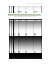
RxD ± Termination/Bias
Install this pair of jumpers to enable a 120 or 150 ohm terminator (model dependent) across the
RxD+ and RxD- pins for the corresponding port. A biasing network is also enabled that drives
the receiver to an inactive or safe mode. The receiver can still receive data from another device
and the biasing helps to prevent the reception of data generated by noise on the transmission
line. The two jumpers for RxD termination/bias must be installed and removed as a pair.
TxD ± Termination
Install this jumper to enable a 120 or 150 ohm resistor (model dependent) across the TxD+ and
TxD- pins of the corresponding port.
Auto 485 (BlueStorm/LP 2 port RS-422/485 models and BlueStorm/SP Opto models only)
Install this jumper to tri-state the transmitters of ports configured as RS-485 half duplex or
multi-drop slave when the computer powers up or is reset. This jumper will be overridden once
JA1
JA2
JA3
JA4
JA5
JA
JB1
JB2
JB3
JB4
JB5
JB
Port 1
Port 2
JC1
JC2
JC3
JC4
JC5
JC
Port 3
JD1
JD2
JD3
JD4
JD5
JD
Port 4
TxD control
RxD control
RxD ± Termination/Bias
RxD ± Termination/Bias
TxD ± Termination
JA
JB
Port 1
Port 2
JC
Port 3
JD
Port 4
RS-485 selection
TxD control
RxD control
RxD ± Termination/Bias
RxD ± Termination/Bias
TxD ± Termination
JA0
JA1
JA2
JA3
JA4
JA5
JB0
JB1
JB2
JB3
JB4
JB5
JC0
JC1
JC2
JC3
JC4
JC5
JD0
JD1
JD2
JD3
JD4
JD5
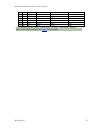
J1 position = +5V power
J2 position = +12V power